Early Beardmore engines were refined Austro-Dainiler designs, which at one time were thought the most efficient airplane engines in existence. Arrol ]ohnston and William Beardmore and Co. were the best known among the several firms that constructed Beardmore engines and parts. Prior to 1916, 90 and 120-hp models were built; afterward, larger engines were needed. Arrol Johnston, Ltd., of Dumfries, Scotland, (a Beardmore Associated concern) developed and later manufactured the 160-hp Beardmore. Although not an exact copy of any Austro-Daimler model, the 160-hp Beardmore still retained the principal features and the same general form. William Beardmore & Co., Ltd. of Parkhead Steel Works, Glasgow, Scotland also developed the B.H.P. Siddeley Puma engines. Aircraft engine development activities flagged following WWI until about 1923, when the firm-began working on large inline water-cooled six-cylinder engines. Little was known of the exact nature of these activities until 1926, when two models appeared. Beardmore built both gasoline and Diesel engines.
As with the Austro-Daimler from which this first design originated, the 90 hp Beardmore bore was 120 mm (4.724″), stroke was 140 mm (5.512″), displacement was 9.5 l (579.7in³) and it made rated power at 1,300 rpm. Six separate vertical water-cooled cylinders’ fuel consumption was 0.54 lb/hp/hr and oil consumption .028 lb/hp/hr.
The 120 hp Beardmore, another six-cylinder vertical water-cooled engine with a 130 mm (5.118″) bore, 175 mm (6.890″) stroke, and a 13.937 l (850.5 in³) produced up to 135 hp at 1,200 rpm. Fuel consumption was 0.54 lb/hp/hr and oil consumption was 0.028 lb/hp/hr. The cylinders were offset 18 mm (0.709″) from the crankshaft centerline in the direction of crankshaft rotation to help reduce piston side loads. The cast-iron cylinders were secured with steel flanges and featured electrolytically-deposited copper water jackets. Both valves were operated by one pushrod, and were held to their seats by laminated leaf springs, a feature of all early Beardmore engines. The exhaust valve seated in the cylinder proper, while the inlet valve seated in a removable valve cage. The inlet valve opened 27.5° late and closed 37° late; the exhaust valve opened 41° early and closed 2.5° early. The six-throw crankshaft on nine plain bearings. The H-shank connecting rods had four-bolt caps. The steel pistons were fitted with three rings. Mixture was furnished by two Beardmore carburetors feeding three cylinders each. A Bosch six-plunger lubricator forced oil to the main bearings, while the connecting rod big ends were splash lubricated. A centrifugal pump circulated cooling water while two H-L-6 magnetos supplied dual ignition. Dry weight was 545 lb.
 |
 |
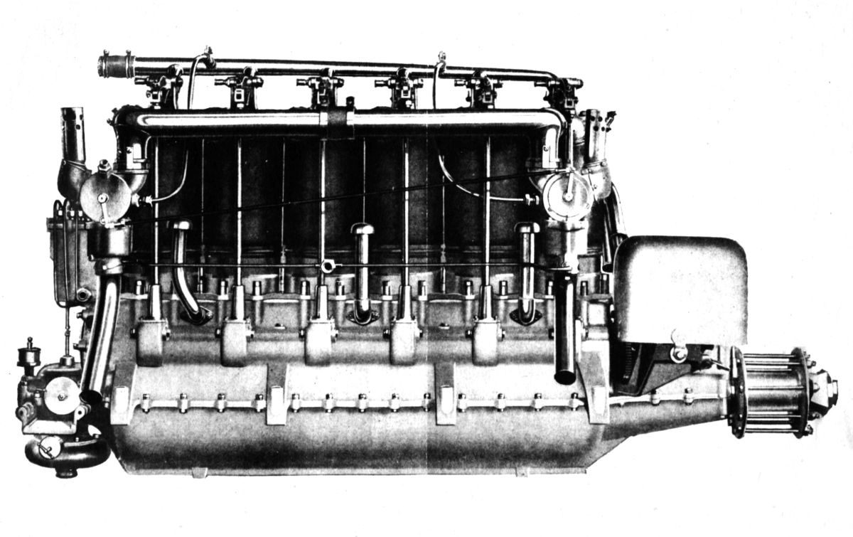 |
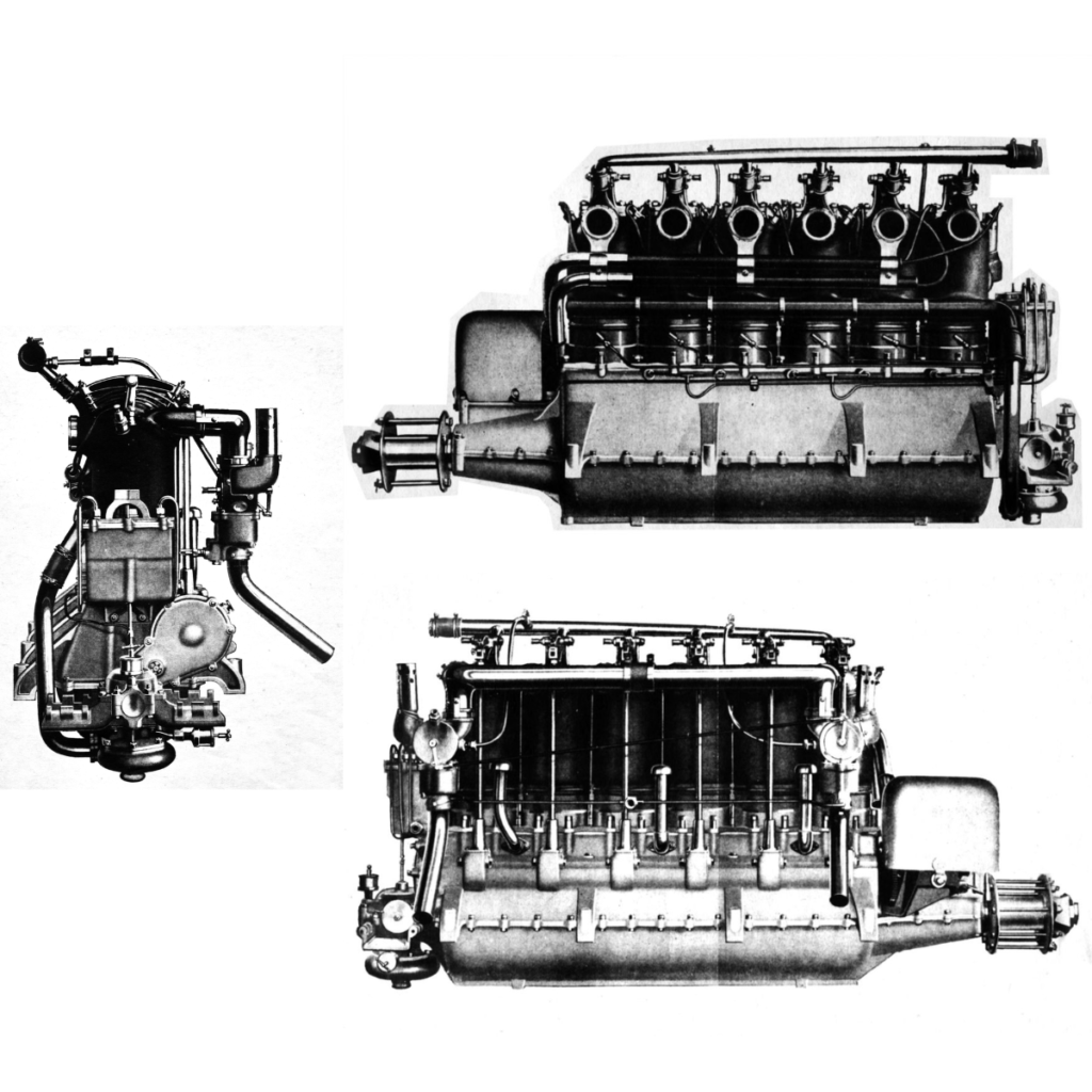
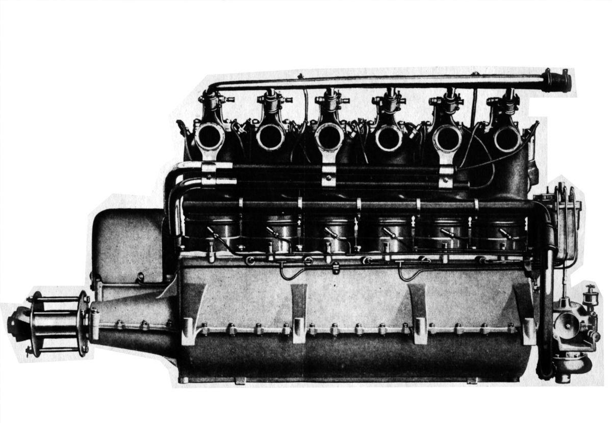
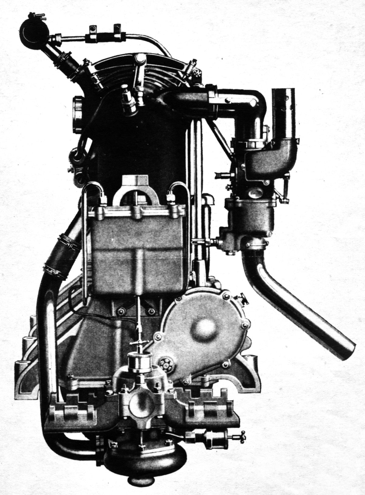
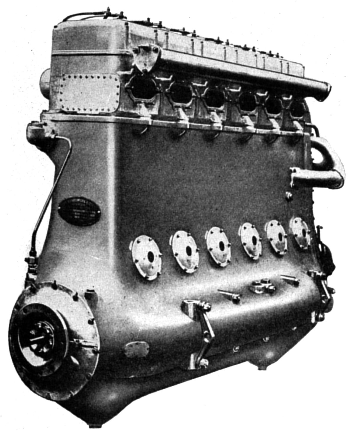
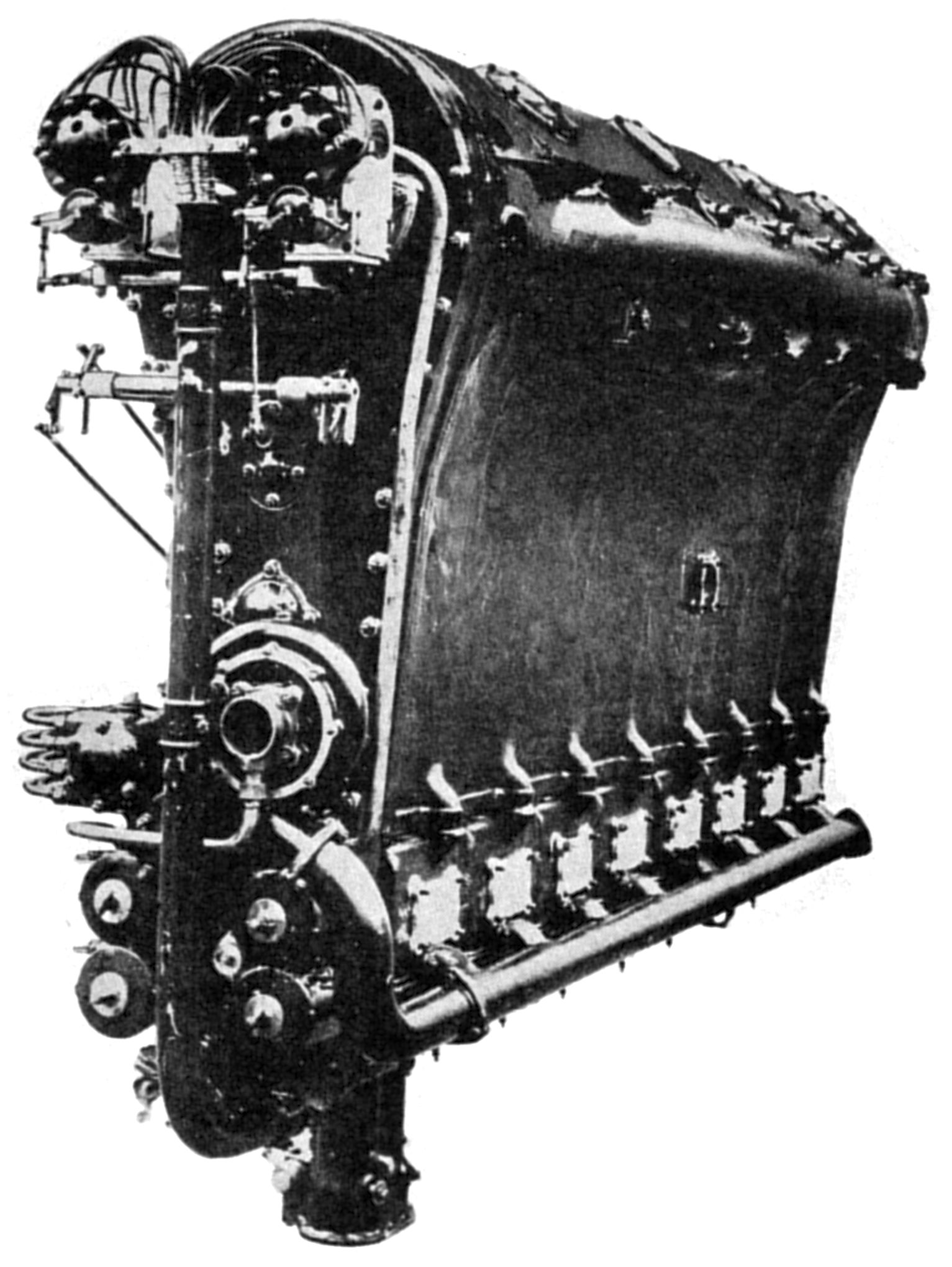
| Beardmore 160 hp Engine (NARA) | ||
The 160 hp Beardmore, a larger six-cylinder vertical water-cooled engine, developed 180 hp at 1,400 rpm. Its bore was 142 mm (5.591″), stroke 175 mm (6.890″), displacement 16.629 l (1,014.8 in³), consumed 0.52 lb/hp/hr fuel and 0.03 lb/hp/hr oil. The 160 hp Beardmore’s design and construction was similar to the smaller engines previously discussed. Its inlet valve opened 26° late, closed 36.75° late; its exhaust opened 45.25° early and closed 4° early. Dry weight was 600 lb and the water in the cylinder jackets weighed 4 lb 7 oz.
 |
 |
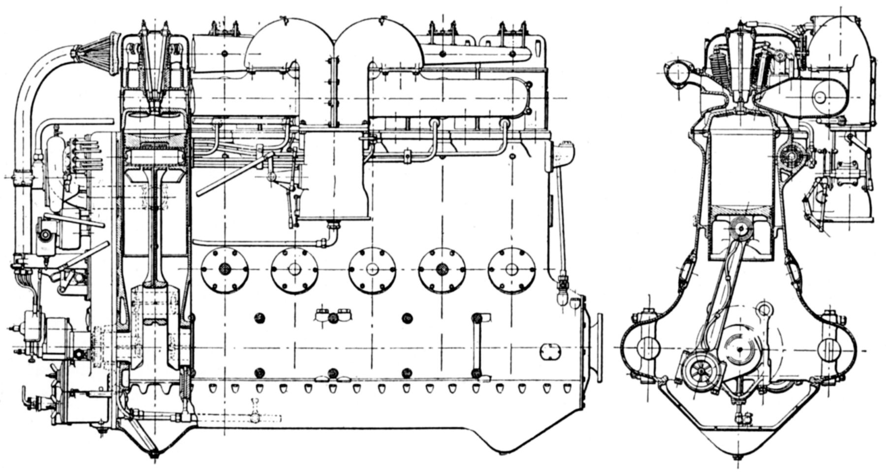 |
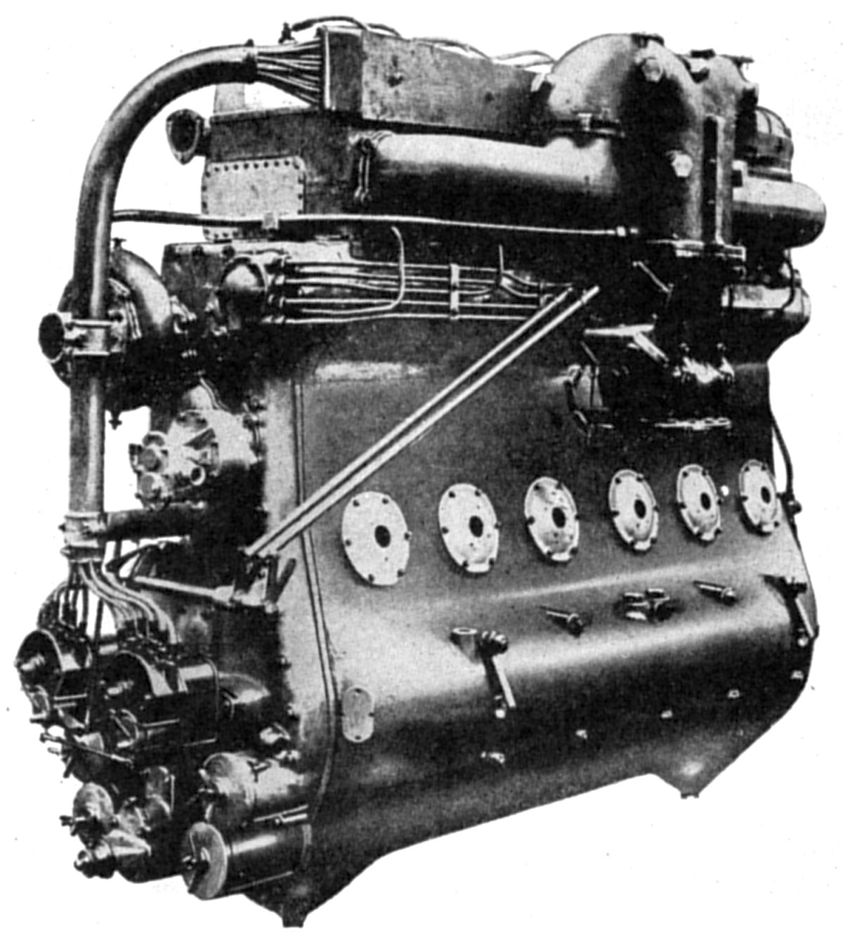
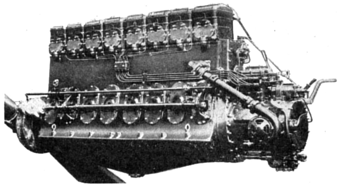
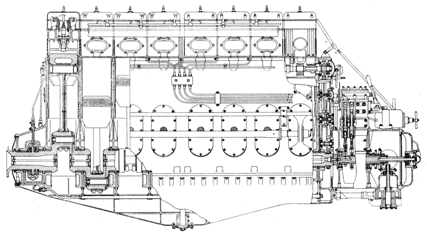
| Beardmore Cyclone Mark II (A39) | ||
The Beardmore Cyclone Mark II engine, a later version of the original six-cylinder vertical water-cooled Cyclone, developed 850 hp at 1,350 rpm with a small carburetor and 950 hp with a large one. With a 8.625″ (219.1 mm) bore and 12.000″ (304.8 mm) stroke, the Cyclone Mark II displaced 4206.7 in³ (68.9 l) and weighed 2150 lb. Compression ratio was 5.25:1, specific fuel consumption 0.48 lb/hp/hr and specific oil consumption 0.01 lb/hp/hr. The Mark II was 80.3″ (2,040 mm) long, 35″ (889 mm) wide, and 60.37″ (1,533 mm) high; height above the crankshaft center line was 42.25″ (1,073 mm). Apparently the design objective was to obtain high output from few cylinders, thereby reducing the parts count while retaining maintenance accessibility. The engine was compact and very clean externally, and featured a small frontal area for the amount of power developed. The aluminum crankcase enclosed the crankshaft and main bearings carried on transverse girders, below which was a removable oil sump. The camshaft was carried in the upper crankcase. Inspection doors opposite each cylinder provided access on both crankcase sides. Thin steel cylinder liners inserted from the crankcase top were sealed at the bottom by a ring at the water space lower end. Each cylinder head with its valve gear formed a separate detachable with two inlet and two exhaust valves actuated by short pushrods and rocker arms. Two spark plugs were fitted in each cylinder head crown. The camshaft was driven by a gear train located in the crankcase rear. These gears also drove the various accessories mounted to the aft gear case, which could be readily detached. An accessory case mounted to the aft crankcase included two Watford magnetos, oil pressure and scavenge pumps, water and fuel pumps, gas distributor, and a gun synchronizer gear when the engine was used for military purposes. Duplex oil filters at the gearcase bottom connected both pressure and scavenging lines, which were provided with change-over valves so that either could he cleaned while the engine was running. Oil was delivered to the main hearings under pressure, and then passed through drilled crankpin passages. Tubular connections strapped to the tubular steel connecting rods shanks delivered oil to the hollow closed-end piston pins. Pistons were made from aluminum forgings, each fitted with three compression rings and one oil-scraper ring. A duplex Zenith carburetor worked in conjunction with a special induction system.
 |
 |
| Typhoon, Simoon (A39) | |
The Beardmore Typhoon was an inverted Cyclone version that weighed 2,233 lb and developed 925 hp at 1,350 rpm. Fuel consumption was 0.48 lb/hp/hr and oil consumption was 0.01 lb/hp/hr. Length was 80.3″, width 38.5″, and the height below crankshaft centerline was 48.525″.
The Simoon was similar to the Typhoon, but it was inverted and had eight water-cooled cylinders. Bore was 8.5625″ (217.5 mm), stroke was 12″ (304.8 mm), displacement was 5,527.9 in³ (85.67 l), compression ratio was 5.25:1, and the dry weight 2,770 lb. It produced 1,100 hp at 1,250 rpm. Fuel consumption was 0.48 lb/hp/hr and oil consumption was 0.01 lb/hp/hr. The Simoon was 98″ (2,489 mm) long, 37.6″ (955 mm), wide, extended 62.325″ (1,583 mm) below the crankshaft center line and 10.275″ (261 mm) above it.
 |
 |
| Beardmore Tornado Mark III (A39) | |
The Tornado Mark III was a compression-ignition engine that resulted from several years of research at William Beardmore & Co. Five Tornados were installed and successfully tested during 1929 in the British airship R-101. This straight-eight had a 8.5625″ (217.5 mm) bore, 12″ (304.8 mm) stroke, 5,527.9 in³ (85.67 l) displacement and developed 585 hp at 900 rpm. Fuel consumption was 0.38 – 0.40 lb/hp/hr and oil consumption was 0.007 lb/hp/hr. It weighed 4,197 lb, or 7.17 lb/hp. Further development, reduced the weight to 4,000 lb. The fuel used had a specific gravity of 0.884 and a flash point (closed) of 166°F. Fuel was directly injected at high pressure by mechanical means to insure good atomization by the centrally-located injector. The latter was of plain outline, in the form of a shallow cylinder, with the atomizer located centrally in the cylinder head. The bmep was 100 psi and the compression ratio 12.25:1. The crankcase was a steel casting with thin steel cylinder liners. Inspection ports in each crankcase compartment were covered with light alloy doors that contained breathers. Pistons were machined from aluminum alloy forgings, and the cylinder heads were aluminum alloy castings with cast-in steel valve seats for the two inlet and two exhaust valves. The lower crankcase face formed the engine support and was closed by an aluminum-alloy oil sump. The crankshaft was carried upon ten white-metal-lined steel shells supported by aluminum main bearing caps. A double Michell bearing between the two end main bearings located the crankshaft and carried the propeller thrust. The main journal diameter was 5.75″ (146 mm) while the crankpin diameter was 4.25″ (107.9 mm). The H-section steel connecting rods were machined all over and featured a strapped-on pipe for piston pin lubrication. The rod big ends had directly-applied white-metal linings, while the small ends carried bronze bushings for the fully floating piston pins. The fuel injection pump was carried on a cylindrical bracket bolted to the engine aft end. This cylindrical bracket carried all the auxiliaries and their drives, such as the oil pressure and scavenging pumps, water pumps, and fuel supply and scavenging pumps, together with the fillers in both lubricating and fuel oil systems. The injection pump was bolted to the bracket top, and its plungers and valves were actuated by an eccentric shaft driven directly from the crankshaft end through air Oldham coupling. The forged steel pump block had cast iron liners for all plungers and reciprocating valves. Fuel pipes led directly to the injectors, which included vent valves to eliminate air trapped in the systerm. A decompresser operated on one inlet valve per cylinder, so that the engine could be motored over to prime the lubrication and fuel systems before actually starting. An auxiliary engine driving a Bendix pinion was utilized for starting. At first, an engine using gasoline for fuel was employed, but later a small compression-ignition engine was developed for starting. The Bendix pinion engaged with a toothed ring at the propeller end where the complete starting gear was enclosed in an aluminum casing. A spur gear train between the fuel pump bracket and crankcase drove the camshaft, which had four cams for each cylinder, each cam operating a roller tappet, push rod and rocker arm. The cylinders were cooled by water boiling and then being condensed with a centrifugal pump providing circulation.
Around 1931, Beardmore started to develop a twelve-cylinder horizontally-opposed high-speed compression-ignition engine for mounting within the leading edge of a thick monoplane wing. This engine developed 500 hp at 1,750 rpm and weighed less than 3 lb/hp. With a 6.0″ (152.4 mm) bore, 6.5″ (165.1 mm) stroke, and 1,102.7 in³ (18.1 l) displacement, the engine drove a propeller at 950 rpm through reduction gears. This engine never entered production.