George Bennie was born near Glasgow, Scotland in 1892 (some say 1891). From a young age, he became interested in rail travel. By the age of 34, he had patented his idea for a new form of public rail transportation. He envisioned a combination airplane and locomotive—an aircraft that flew on rails. This vehicle would be capable of high speeds and would operate independently of standard rail transportation.

A poster forecasting the George Bennie Railplane (G•B•R) line.
In his System of Aerial Transport patent from 1923, Bennie describes a vehicle suspended between two rails positioned above the ground. A single bogie attached the vehicle to the upper rail. This rail would support the vehicle while it was at rest and at slow speeds. The lower rail would stabilize the vehicle via a set of guide wheels at each end of the carriage and would also prevent the body from swinging out as it traveled around curves.
A propeller was situated at each end of the vehicle. In the patent, only one of the fixed pitch propellers would be used to pull the vehicle along the track. The propeller at the opposite end would be used for breaking or pulling the vehicle in the opposite direction. The propellers could be driven by internal combustion engines or by electric motors powered via an electrified rail. As the vehicle’s speed increased, lifting planes positioned on the roof would support some of the craft’s weight, increasing its efficiency by decreasing the friction from the rails.

The Railplane moves away for the platform along the short test line.
Working with consultant engineer Hugh Fraser, Bennie’s vision became a reality in 1929. A test track for the George Bennie Railplane System of Transport, also known as the Railplane Line, was built in Milngavie, near Glasgow. The test track was about 425 ft (130 m) long and was built over a section of the London and North Eastern Railway (LNER) line. The elevated track was built by Teesside Bridge and Engineering Company. It had a 16 ft (4.9 m) vertical clearance above the railway (standard bridge clearance at the time), and each of its five spans was 80 ft (24.4 m) long. The elevated track would allow the Railplane to traverse geography not traditionally covered by a standard railroad track. In addition, utilities such as telephone and electricity could be incorporated into the elevated track.
The Railplane test car differed from the original patent in a number of ways. No lifting planes were incorporated into the Railplane, and it was suspended from the upper rail by two bogies. The bogies had laminated springs to dampen the ride. The two-blade, 9 ft (2.7 m) propellers worked together to send the Railplane along the line. Electric motors were used and they received their power through the rail. The motors provided a continuous 60 hp (44.7 kW) at 1,200 rpm but could be operated at 240 hp (179 kW) for up to 30 seconds. For braking, the propellers’ rotation could be reversed and the bogies had provisions to grip the rails.

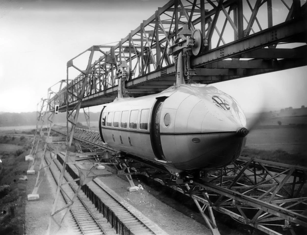
The Bennie Railplane on its elevated track as seen from the ground. The two-blade propellers can be see on both ends of the Railplane.
The Railplane test car was built by William Beardmore & Company Ltd. It was skinned in aluminum over an aluminum frame with a steel keel. The Railplane was 52 ft (15.8 m) long, 8 ft (2.4 m) in diameter, and weighed 12,000 lb (5,443 kg) complete. Two sliding doors with stained glass windows allowed passengers to enter and exit the Railplane. The plush interior of its 24 seat passenger area was outfitted by Waring & Gillow.
On 8 July 1930, the Railplane Line was officially opened to the press and invited members of the public. Although the rail and subsequent ride were short, they did illustrate the service a full Railplane Line would provide. It was noted that the Railplane was very smooth in both acceleration and ride. Bennie estimated the top speed of the Railplane as 120 mph (193 km/h). However, higher speeds could be obtained with increased power to the propellers.

The plush interior of the Railplane which accommodated at least 24 passengers.
Other power arrangements were proposed. The Railplane’s electric motors could be powered by an onboard internal combustion engine connected to a generator. Alternatively, internal combustion engines could be directly connected to the propellers. Bennie also designed a way to couple multiple Railplanes together via their propeller hubs. It appears this system incorporated a four-blade propeller with an extended hub. A single engineer in the lead Railplane would control all of the propellers.
A Railplane Line was seen as a way to ease congestion by operating above and much faster than freight trains. Although there was considerable interest and various Railplane Line proposals, no main financial backers were found, and none of the proposals moved forward. By 1937, Bennie was bankrupt and the Railplane was abandoned. The Bennie Railplane track and carriage remained in place until 1956, when it was disassembled and scrapped.

The Railplane outfitted with a four-blade propeller and a special hub to couple to another Railplane.
In the intervening years, Bennie continued with the Railplane concept. In 1946, the George Bennie Airspeed Railway Ltd was founded, followed by the George Bennie Airspeed Railway (Iraq) Ltd in 1951. As with the original Bennie Railplane Line, these endeavors failed to move forward. George Bennie passed away in 1957, never having achieved his goal of creating a high speed public rail system.
Below is a video of the Bennie Railplane in action uploaded to YouTube by British Pathé.