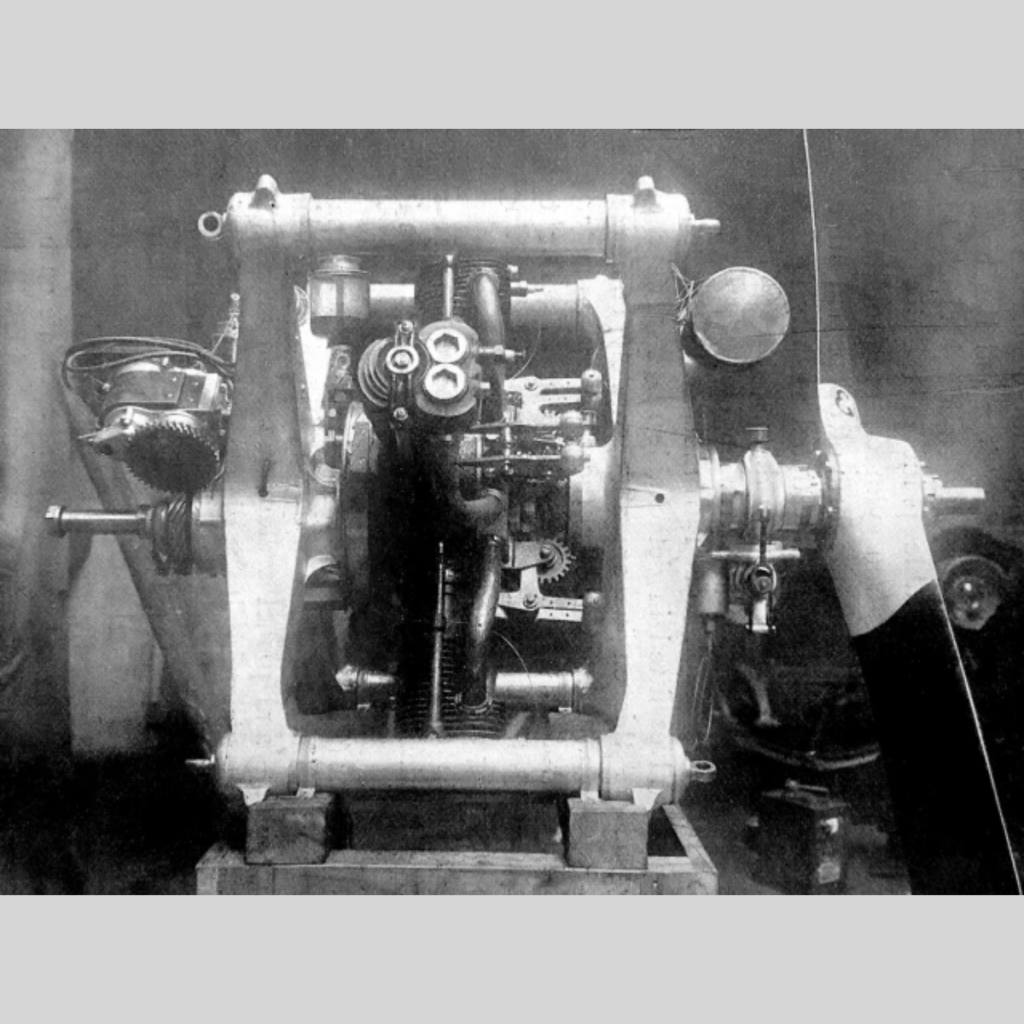

Charles (Carl) Deissner stands next to the 30 hp (22 kW) Paradox engine during a test run. The frame around the engine enabled it to be run in such demonstrations and was not needed when the engine was installed in an aircraft (which probably never happened). Note the carburetor at the front of the engine.
As early aviators began to take flight, it quickly became apparent that most engines were not suitable for use in aircraft. A number of engineers and designers worked to create light and powerful engines that were ideal for aircraft use. Some of these designs, such as the Antoinette, lay the foundation for many engines to follow, but other engine designs were quickly abandoned. Like many others, Charles (Carl) Deissner of London, England designed one of the engines destined to go nowhere. Deissner called his engine the Paradox.
The Paradox was an air-cooled, four-cylinder, four-stroke, rotary engine. In this context, “rotary” refers to a radial engine in which the crankcase and cylinders rotate around the crankshaft. This is not to be confused with a Wankel engine, which uses a rotor spinning in a fixed crankcase to produce power. Most rotary aircraft engines had the crankshaft fixed to the airframe, while the propeller was attached to and spun with the crankcase. However, the Paradox was not like other rotary engines.
While the crankcase of the Paradox rotated just like any other rotary engine, inside the Paradox, the crankshaft turned at twice the speed of the crankcase and in the same direction. The engine’s internals were kept in order by eccentric gears on the crankshaft engaging ring gears inside the crankcase. The stroke of the crankshaft represented one quarter of the piston’s stroke. The path of the eccentric gear also represented one quarter of the piston’s stroke. The relative motions of the crankcase and crankshaft enabled the full stroke to be utilized and allowed the unique Paradox engine to function.

Sectional view of the 30 hp (22 kW) Paradox engine. The valves can be seen on the front of the L-head cylinders. Below the valves are the pushrods actuated by counter-weighted rockers. The rockers are driven by a short camshaft extending on each side of a pinion. The pinion rotates as its teeth mesh with a gear fixed to a stationary shaft at the front of the engine.
The easiest way to visualize the Paradox engine’s operation is to consider the piston at the top of the cylinder when the cylinder is at the 12 o’clock position. Here, the crankshaft and its throw are at top dead center. When the engine has rotated 180 degrees, putting the cylinder at the six o’clock position, the crankshaft has rotated 360 degrees. The crankshaft is again at top dead center, but since the cylinder is now at the bottom of the engine, the piston is now at the bottom of the cylinder. When the engine has rotated another 180 degrees, the cylinder is back at the 12 o’clock position, and the crankshaft, having rotated 360 degrees, is again at top dead center, returning the piston to the top of the cylinder.
The crankshaft had two throws 180 degrees apart, and each throw served a pair of cylinders. The cylinders of each pair were 180 degrees apart, and the two cylinder pairs were 90 degrees apart. A non-articulating, solid connecting rod served each cylinder pair so that when one piston was at the top of the cylinder, the piston in the opposite cylinder was at the bottom of the cylinder. Deissner stated that since the connecting rod did not articulate, Paradox engines could be made with relatively long strokes and achieve high compression ratios.

The 30 hp (22 kW) Paradox engine complete with propeller. Note the skew gear-driven magneto, counter-weighted rocker arms, and the cylinders’ L-head design.
Three versions of the Paradox engine were planned for construction with different outputs: 30 hp (22 kW), 70 hp (52 kW), and 100 hp (75 kW). However, it appears only the 30 hp (22 kW) and 70 hp (52 kW) engines were actually built. While both engines had four cylinders and shared the same rotary and eccentric crankshaft arrangement, each engine also had a number of unique features.
The 30 hp (22 kW) Paradox was a demonstration engine mounted in a metal frame. The engine utilized an L-head cylinder with side valves. The single intake and exhaust valves were positioned on the front side of the cylinder. Each valve was actuated by a pushrod driven by a large, counter-weighted rocker arm. Part of the rocker rode on a camshaft that extended through the axis of a pinion. The cam on one side of the pinion controlled the intake while the cam on the other side controlled the exhaust. The pinion was driven by a skew gear mounted on a stationary shaft that did not rotate with the engine.
Induction air was brought in through a carburetor at the front of the engine. The air/fuel mixture then passed through the crankcase, where it was warmed, and into separate manifolds for each cylinder. Exhaust was taken through a manifold from each cylinder, piped through the crankcase, and vented out the front of the engine’s propeller shaft, which was fixed to the crankcase.

Schematic view of the induction and exhaust system in the 70 hp (52 kW) Paradox engine. For clarity, the valves are illustrated on the front and rear of the T-head cylinder, rather than its sides. Note the offset crankshaft.
A magneto was driven by a skew gear at the rear of the engine. The magneto fired the one spark plug installed in each cylinder. However, it appears the engine could accommodate two spark plugs per cylinder. Ball bearings were used throughout the engine. The 30 hp (22 kW) Paradox engine had a 2.76 in (70 mm) bore and a 7.17 in (182 mm) stroke. The engine displaced 171 cu in (2.8 L). Its 30 hp (22 kW) output was obtained at 1,200 rpm. Increasing the engine’s rpm to 1,400 resulted in an output of 40 hp (30 kW).
The 70 hp (52 kW) Paradox engine also used side valves but in a T-head arrangement, with the valves on opposite sides of the cylinder. The valves were actuated by the same method used on the 30 hp (22 kW) engine, but a pushrod and rocker was now positioned on each side of the cylinder. One schematic shows the valves on the front and back sides of the cylinder, rather than the left and right sides. This was most likely done for illustrative purposes, to show how the engine’s induction and exhaust systems worked. Induction air was brought in the front of the engine, passed through the crankcase (where it was warmed), and flowed through a fixed shaft at the rear of the engine. Here, it passed through a carburetor, and the air/fuel mixture flowed back through the shaft to manifolds at the rear of the engine; these manifolds led to each cylinder. The 70 hp (52 kW) Paradox engine had a 4.0 in (102 mm) bore and a 7.0 in (178 mm) stroke. The engine displaced 352 cu in (5.8 L). Its 70 hp (52 kW) output was obtained at 1,400 rpm, and it produced 60 hp (45 kW) at 1,200 rpm. The engine weighed 220 lb (100 kg).

1910 advertisement for the Paradox engine expressing its many virtues over other rotary engines. The pricing for the 70 hp (52 kW) engine is given, although the 30 hp (22 kW) engine is illustrated in the photograph. The price of the 70 hp (52 kW) engine was increased to £460 in March 1911. (via www.aviationancestry.co.uk)
The 30 hp (22 kW) Paradox engine was running by late 1910. It was run both with and without a 7 ft 6 in (2.3 m) Eta propeller. Some of the engine’s noted advantages were that standard lubricating oil could be used—other rotaries typically needed castor oil. The Paradox engine was also said to have good fuel economy, but no specifics were given. In early 1911, the 30 hp (22 kW) engine broke free during a test run, resulting in a destroyed propeller and a damaged engine. The engine was repaired in February, and the 70 hp (52 kW) Paradox engine was to be finished by March 1911. However, no further information has been found regarding any Paradox engine.
The Paradox engines may have offered some improvements in oil consumption, which was always quite high with standard rotaries, but its other unique features did not offer any tangible advantage over more popular engines. Rotary engines would continue to be widely used until after World War I. At that time, conventional engines had out-powered the rotary, and the inherent limitations of its spinning crankcase design could not be overcome.