The naval arms races of the first half of the 20th century are characterized by virtually every major naval power embarking on battleship construction programs that sought to outclass rival navies with regard to speed, armor, and gun power. The Japanese were no exception and went with the philosophy of “bigger is better.” According to the U.S. Naval Technical Mission to Japan (1946), “Shortly after World War I, Kure Naval Arsenal and the associated Kamegakubi Proving Ground began work on a 48cm (18.9-inch)/45 caliber gun” (p. 9). Two test guns were constructed, both of which were wire wound near the breech. The first gun split during test firings, but the second gun remained at the proving grounds and was found at the end of the war. Both were copies of a pre-WWI British 15″ design. With the passing of the Washington Naval Treaty, work on these guns stopped (U.S. Naval, 1946, p. 9).
Design work on large caliber guns in Japan recommenced in 1934 along with the design studies of the Yamato-class battleships. Design work on the guns and mounts was led by the engineer C. Hada who designed most of the large caliber guns of the IJN for the 40 years prior to his death in 1943. The previous 48cm guns were deemed too heavy, but it was decided that 46cm (18.1″) guns could give Japanese battleships a definite advantage over the U.S. 16″ guns. The gun (more correctly, the breech) was designated Type 94 after the year of the design (1934 in the Japanese Imperial calendar was the 2594th year since the first Emperor of Japan, hence Type 94). Design work was finished and production began in 1939-1940. To keep the actual size of the gun a secret, it was always referred to as the 40cm (15.7″)/45 Type 94 (U.S. Naval, 1946, p. 9). Indeed, the Americans did not know of their true size until the end of the war. Garzke and Dulin (1985) note that the Japanese briefly considered using 16.1″/45 guns as an alternative, but were expecting to fight more enemy ships at longer ranges than European battleships. Eventually, the 18.1″ guns were chosen over the 16.1″ due to their greater performance characteristics (p. 88).
The guns themselves weighed in at 165 metric tons and each turret weighed 2,774 metric tons. To give some idea as to the size of these turrets, most destroyers of that era had a similar displacement (Garzke & Dulin, 1985, p. 89). All guns (27 in total) and mounts were constructed by the Kure Naval Yard’s Ordnance Department under the guidance of engineers M. Okayama and Admiral T. Ito. Six complete mounts went to the battleships Yamato and Musashi. One trial mount was built to test turret machinery and numerous parts for Shinano’s mounts were completed. 18 of the guns went down with the sinking of Yamato and Musashi. Since Shinano was converted to an aircraft carrier prior to completion, the nine guns slated for her were discovered by the Allies in various stages of completion at Kamegakubi Proving Ground at the end of the war. Two were destroyed in November of 1945 and two were taken to Dahlgren Proving Grounds in the U.S. for ballistic tests (U.S. Naval, 1946, p. 9).
| Ship Class Used On: | Yamato-class battleships |
| Date In Service: | 1941 |
| Gun Weight: | 363,000 lbs (164,654 kg) w/breech |
| Gun Length (overall): | 831.9 in (21.13 m) |
| Bore Length: | 815 in (20.7 m) |
| Twist: | uniform RH 1 in 28 |
| Chamber Volume: | ~41,496 cu in (680 cu dm) |
| Rate of Fire: | 1.5-2 rounds/minute |

1/10th scale model of Yamato’s & turrets.

1/10th scale model of Yamato as seen from front.

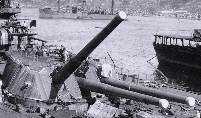
Yamato nearing completion at Kure Naval Yard.
The above left and center photos are from my trip to the Yamato Museum in Kure, Japan in 2015. The main exhibit of this museum is a massive 1/10th scale model of the Yamato battleship in her late-war configuration.
The guns were similar in construction to the British 15″/42 caliber Mark I and the Japanese 16.1″/45 caliber. They were of a wire-wound, radially expanded construction with a screw-type breech. The Japanese favored durability and reliability over ballistic performance in their gun designs (Garzke & Dulin, 1985, p. 89).
| Weight: | 2730.2 tons (2,774 mt) |
| Elevation: | -5 to +45 degrees |
| Elevation Rate: | 8 degrees/second (sources differ plus/minus 2 degrees) |
| Train: | About -150 to +150 degrees |
| Train Rate: | 2 degrees/second |
| Recoil: | 56.3 in (1.43 m) |
| Loading Angle: | +3 degrees |
| Armor Thickness: | 25.6″ face; 9.8″ sides; 7.5″ rear; 10.6″ roof |

Cutaway model of an 18.1″ gun turret (1/50th scale).

Port side gun of cutaway model has been elevated.

Diagram of an 18.1″ gun turret and magazine.(Photo credit: Skulski, 2017, p. 224)

Diagram of 18.1″ gun turret from above.(Photo credit: Skulski, 2017, p. 225)
The magazines were located around the upper and lower cordite handling rooms. The lower magazine supplied the center gun only. Above the magazines were the shell and handling rooms. 180 rounds (60/gun) were stored in the rotating turret structure. The Japanese considered that sufficient for the average surface engagement. The remainder were stored in the lower handling rooms and were moved around by a unique push-and-pull type geared mechanism. Pusher-type hoists loaded in either handling room moved the shells up to the gun house where they were then tilted horizontally. However, the movement of shells was extremely slow. Cordite was loaded in six equal charges by one stroke. Separate rammers handled the shells and cordite. It has been noted that the Japanese relied on well-drilled crews and fewer safety interlocks to prevent accidents when compared to other navies (Garzke & Dulin, 1985, p. 90). One such accident that resulted in the death of a crew member occurred when he was cut in two by a shell bogie in the space between the shell and shell handling room. It was ruled that his own carelessness was to blame (U.S. Naval, 1946, p. 58).
| Type: | Bag |
| Projectile Types & Weights: | Type 91 APC: 3,219 lbs (1,460 kg)Type 0 Common HE: 2,998 lbs (1,360 kg)Type 3 Common AA: 2,998 lbs (1,360 kg) |
| Bursting Charge: | Type 91 APC: 74.6 lbs (33.85 kg)Type 0 Common HE: 136 lbs (61.7 kg)Type 3 Common AA: N/A |
| Projectile Length: | Type 91 APC: 76.9 in (195.35 cm)Type 0 Common HE: 63 in (160 cm)Type 3 Common AA: 63 in (160 cm) |
| Propellant Charge: | 794 lbs (360 kg) in six bags |
| Muzzle Velocity: | Type 91 APC: 2,559 fps (780 mps) Type 0 Common HE: 2,641 fps (805 mps) Type 3 Common AA: 2,641 fps (805 mps) |
| Working Pressure: | 19-20.3 tons/sq. in (3,000-3,200 kg/sq. cm) |
| Barrel Life: | About 150-200 rounds |
| Ammo stowage/gun | 100 rounds (300 per mount) |

A display of shells in the Large Exhibits Room of the Yamato Museum in Kure, Japan. I have labeled the shell types.

(Photo Credit: U.S. Naval Technical Mission to Japan Report O-19 “Japanese Projectiles General Types”, p. 31.)
The Type 91 armor-piercing shell was manufactured in multiple different calibers and all were painted white with an orange band indicating the center of gravity. The red and green tip on the windshield indicates that the projectile is base-fuzed. The 18.1″ Type 91 projectiles had a fuze delay of 0.4 seconds which would be triggered upon impact with the water and allow time for the shell to impact the target (U.S. Naval O-19, 1946, p. 32). In order for the ships to visually identify the fall of their AP shells, each had a specific color of dye bag that would color the shell splashes. No color was assigned for Yamato and green dye was assigned for Musashi (DiGiulian, 2019).
David Evans and Mark Peattie (1997) write that the Type 91 shell stemmed from firing tests on the incomplete battleship Tosa in 1924. From these tests, the Japanese came upon the concept of underwater shots ( 水中弾 suichudan). During the gunnery tests, it was discovered that 16″ shells fired at 20,000 meters, entering the water at an angle of 17 degrees, and 25 meters short of the target would penetrate the hull below the armor. Further testing showed that a shell with a flat head could enter the water at 17 degrees as far as 80 meters from the target and still penetrate. The best results were shown to be at a distance of 40 meters from the target (p. 263).
The Type 91 shell was designed to be dual-purpose. It was capped to penetrate in the event of a direct hit. In the case of impacting the water short of the target, the windshield of the shell was designed to break off exposing the flat cap head and allowing the shell to maintain its trajectory through to water to the target and penetrate the hull underneath the belt armor. In line with the design of the shell, the Japanese fire control doctrine stressed shots falling just short of the target, if not achieving direct hits. It was also believed that if the shell passed underneath the target, the time-delay fuze would still allow it to detonate underneath the keel (Evans & Peattie, 1997, p. 263). There has been skepticism by experts with regard to whether or not the idea of underwater shots would have been very effective. Due to the top-secret nature of the shell and its use, underwater shots were never practiced in peacetime training. Furthermore, the shells were only effective at a range of about 20,000 meters and there were few gun battles historically which occurred at those ranges. Whether or not American intelligence was aware of the Type 91, U.S. battleships following the North Carolina-class were designed to resist underwater hits (Evans & Peattie, 1997, p. 263 – 266). Report O-19 of the U.S. Naval Technical Mission (1946) concluded that the Japanese “sacrificed the effectiveness of their AP projectiles on occasions of direct hitting (particularly against light armor) in order to achieve a doubtful hit through the water or a mining effect for which an AP projectile is singularly poorly designed” (p. 1).

(Photo Credit: U.S. Naval Technical Mission to Japan Report O-19 “Japanese Projectiles General Types”, p. 10.)
Report O-19 of the U.S. Naval Technical Mission to Japan (1946) notes that there was nothing unique to the Type 0 Common HE shells. The differences between the different calibers were the manufacturing requirements and available machinery. These shells were normally painted maroon in color and given timed fuzes for anti-aircraft use (p. 7 – 9).

Diagram of the Type 3 Common AA shell(Photo Credit: U.S. Naval Technical Mission to Japan Report O-19 “Japanese Projectiles General Types”, p. 14.)
Many Japanese warships were equipped with a particular type of anti-aircraft shell for their main guns known as the Type 3 Common shell (三式焼霰弾 literally: Type 3 “burning hail” shell). The Type 3 shells for the Yamato-class battleships had more than 900 tubes filled with an incendiary mixture. These had a time mechanical fuse and were designed to burst approximately 0.5 seconds after exiting the muzzle creating a 20-degree cone of flaming material. The incendiary material burned at approximately 3,000 degrees Celsius for five seconds and created a five-meter-long flame (U.S. Naval O-19, 1946, p. 8 – 14). Actual combat use demonstrated that these shells were not particularly useful and U.S. naval aviators reported that they looked more like fireworks than a serious threat (DiGiulian, 2019).
Note on Armor Penetration Values:
Garzke and Dulin (1985) derived the penetration values from “a detailed U.S. Navy empirical equation” modeled against U.S. Class B Homogeneous armor. The values are noted as not being precisely correct but should give an accurate measure of performance (p. 495). For a further examination of the Garzke and Dulin data, see the following article: The Garzke and Dulin Empirical Formula for Armor Penetration.
- Shell Type & Weight: Type 91 APC 3,219 lbs (1,460 kg)
- Muzzle Velocity: 2,559 fps (780 mps)
| Range | Armor Penetration |
| 0 yds | 34.06″ (865 mm) |
| 21,872 yds (20,000 m) | 19.48″ (495 mm) |
| 32,808 yds (30,000 m) | 14.22″ (361 mm) |
Historically, there were larger guns out there, but none mounted afloat or put into active service in any navy. Although the mounts and guns saw a short service of three years, the designers were impressed by their performance. Given the massive construction of the machinery, they expected to find more issues, but also noted that such teething problems usually surfaced within the first few years of service. Some problems experienced were the large amounts of lubricating oils required (for the hoist racks, winches, and training gears), the noise made by the mount rollers, the difficulty in hoisting shells when the ship was rolling more than 5 degrees, and the sheer amount of blast felt from the guns around the bridge area (U.S. Naval, 1946, p. 57 – 58). During the test firings of the Musashi‘s guns during her sea trials, engineers placed instruments to measure blast pressures, as well as cages of guinea pigs on the deck. An examination following the tests showed that the guinea pigs had literally been blown apart. Witnesses on the bridge reported that the firing of the guns produced a tremendous shock wave that felt, “as if their guts had suddenly been thrust upwards into their throats” (Yoshimura, 1999, p. 126 – 127). Blast pressures of 7 kg/sq. cm. (~100 psi) was measured at 15 meters from the muzzles when firing all three guns in any one turret. A man would be temporarily knocked out at pressures of 1.16 kg/sq. cm. (~16 psi) and pressures of 0.28 kg/sq. cm. (~4 psi) was enough to destroy the ship’s boats. Thus, all anti-aircraft weapons mounted near the main turrets required blast shields (Garzke & Dulin, 1985, p. 93). It is likely that the anti-aircraft guns mounted on top of the turrets would not be manned while the main battery was in operation.
Skulski and Draminski (2017) tabulated the following blast pressures for the 18.1″ guns:
| 1 barrel | 3 barrels |
|---|---|
| 10.0 kg/sq. cm. @ 5m | 20.0 kg/sq. cm. @ 5m |
| 5.5 kg/sq. cm. @ 10m | 11.0 kg/sq. cm. @ 10m |
| 3.1 kg/sq. cm. @ 15m | 7.0 kg/sq. cm. @ 15m |
Reportedly the blast from the guns was powerful enough to rip the clothes of a person, although that is probably anecdotal or apocryphal. More likely, anyone standing in an unprotected position near the guns when they fired would be severely injured or outright killed by the blast. At that point, having your clothes torn off your body is pretty moot.
The Japanese put considerable work into the fire control systems to achieve a low dispersion when the main guns were fired. The turrets were designed to minimize the recoil in the elevation and training gears. Furthermore, the Type 98 Firing Device created a delay so that adjacent guns would not fire simultaneously (Garzke & Dulin, 1985, p. 90). Dispersion for these guns when firing four to five gun salvos at the maximum range was around 500 – 600 yards. Full broadsides had larger spreads (U.S. Naval, 1946, p. 58). Tony DiGiulian (2019) notes a different dispersion of 440 – 550 yards at maximum range.
While the guns were extremely large, the Japanese were capable of building even larger ones such as the previously mentioned 18.9″ test guns. In fact, they began construction on 20.1″ guns for the proposed A-150 design AKA Super Yamato-class (Garzke & Dulin, 1985, p. 85). One of the manufacturing issues with these 18.1″ guns was that they were of very complex construction. DiGiulian (2019) notes that the inner A tube would need to have been completely bored out to reline the guns. Since this was expensive, it would have been more practical to simply replace the entire gun itself. However, there is no evidence that Yamato or Musashi ever had their guns replaced.
Yamato fired on enemy ships only once in her career during the Battle off Samar, although whether or not she hit anything with her 18.1″ shells is debatable. Torpedoes from a charging U.S. destroyer forced her to turn away from the battle. Apart from that, she also fired Type 3 Common anti-aircraft shells at U.S. aircraft during her final sortie. Musashi likewise is only known to have fired at enemy aircraft with Type 3 Common shells during her final battle in the Sibuyan Sea. Reportedly, the turret was put out of action when a Type 3 Common shell either exploded or became stuck in one of the barrels (Garzke & Dulin, 1985, p. 70).
Comparisons with the U.S. 16″/50 Mk 7 guns used on the Iowa-class battleships show slightly better armor-piercing capabilities for the Japanese 18.1″/45, but ballistic tests conducted by the U.S. Navy would seem to indicate that the Japanese 18.1″ guns were, by and large, mediocre for their caliber (Garzke & Dulin, 1985, p. 89). See this post for a comparison between these two guns.
Coming to a concrete evaluation of these guns is no easy task. Since none of these guns exist anymore and are unlikely to ever be constructed again, we have only the surviving data, mathematical models, and the opinions of experts to go off of. The existing data is fairly old and much of the exact details on the Yamato-class battleships were lost in the firebombings or when the Japanese Navy burned a substantial number of documents to prevent them from falling into Allied hands at the end of the war. Thus, at present, an objective evaluation is extremely difficult.