In 1928, independent aircraft engine designer Frank Bernard Halford was contracted by D. Napier & Son (Napier) to design aircraft engines with a displacement between 404.09 and 718.37 cu in (6.62 and 11.77 L). Halford’s first designs for Napier were the H-16 Rapier (Napier designation E93) of 1929 followed by the inverted I-6 Javelin (Napier designation E97) of 1931.

The Napier Dagger I air-cooled H-24 with its downdraft carburetor and propeller shaft in line with the engine’s centerline. “Napier Halford” can be seen on the upper camshaft housing. Note the two engine mounts on the side of the crankcase and third mount on the accessory housing. (Napier/NPHT/IMechE image)
Around 1932, Halford and Napier reached a new agreement, and the design of engines larger than the 718.37 cu in (11.77 L) limit were initiated. The first of these designs was a 24-cylinder development of the Rapier with an enlarged bore and elongated stroke. This engine was named the Dagger, and it carried the Napier designation E98. The engine was also called the Napier-Halford Dagger. Like the Rapier, the air-cooled Dagger was a high-revving aircraft engine with numerous small cylinders and minimal frontal area. Halford’s belief was that a smaller engine running at higher speeds would produce the same power as a larger engine running at slower speeds.
The Dagger had a vertical H configuration with four cylinder banks, each with six cylinders. The two-piece aluminum crankcase was split horizontally at its center. The two crankcase halves supported left and right crankshafts via seven main bearings each. An eighth crankshaft bearing was located in the gear reduction housing. Each one-piece, six-throw crankshaft served one vertical and one inverted bank of cylinders. The crankshafts were phased at 30 degrees with power strokes occurring sequentially between the two crankshafts. The connecting rods were of the fork-and-blade type, with the forked rods serving the upper front three cylinders on the left side of the engine and the upper rear three cylinders on the right side of the engine. Spur gears at the front of each crankshaft meshed with a larger gear mounted to the propeller shaft, which turned at .372 crankshaft speed. When viewed from the rear, both crankshafts rotated clockwise, and the propeller shaft rotated counterclockwise.

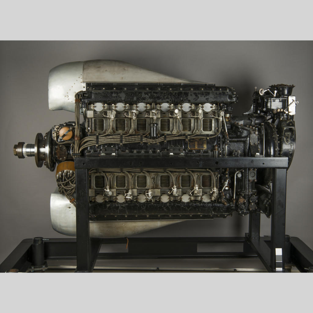
A Dagger II engine preserved and in storage as part of the Smithsonian National Air and Space Museum. The engine appears complete with its upper and lower air ducts as well as the baffling around the cylinders. At one time, this particular Dagger II belonged to the US Navy. The engine data plate says “Halford-Napier Dagger.” (NASM image)
The individual cylinders were made from forged steel barrels with cast aluminum heads. The heads for each cylinder bank were first installed to a common camshaft housing and then drawn down on the cylinder barrels via four studs protruding from the crankcase around each cylinder opening. An aluminum sealing ring was sandwich between the cylinder head and barrel. The cylinders had a 7.75 to 1 compression ratio, and each cylinder had a single intake and a single sodium-cooled exhaust valve. The intake port was on the inner side of the cylinder, and the exhaust port was on the outer side. The valves for each cylinder bank were actuated via rockers and tappets by a single overhead camshaft. The self-adjusting hydraulic valve tappets were designed by Halford. Each camshaft was driven via a vertical shaft and bevel gears from the rear of the engine.
Each cylinder had one spark plug mounted on its outer side and another mounted on its inner side. The spark plugs were fired by two magnetos mounted to and driven from the gear reduction housing. An accessory drive case was mounted to the back of the engine. A shaft extending back from the propeller shaft powered the accessory drive case. Driven from the accessory case were the camshafts, supercharger, generator, oil and fuel pumps, and various accessories. The single-speed supercharger drew in air through a downdraft carburetor and compressed the air and fuel mixture with a centrifugal impeller. The air and fuel mixture exited the supercharger housing via upper and lower passageways in the crankcase. These passageways were located between the upper and lower cylinder banks, and each had six outlets. A T-shaped manifold that was attached to each induction passageway outlet delivered the air and fuel mixture to two cylinders, one on each bank.

A Dagger III with individual exhaust stacks and many components chromed and polished to perfection for display purposes. Note the “Napier Halford” placard on the upper camshaft housing. (Napier/NPHT/IMechE image)
For engine cooling, air was ducted between the upper and lower cylinders. Baffles directed the air’s flow through the cylinders’ integral cooling fins and to the outer side of the cylinder banks. The cooling air exited via a cowl flap on each side of the aircraft and behind the engine. Two engine mounting pads were incorporated into the crankcase on each side of the engine. Two integral pads on each side of the rear accessory case were used together to form a third engine mount.
The Napier Dagger I (E98) had a 3.8125 in (96.8 mm) bore and a 3.75 in (95.3 mm) stroke. Each cylinder displaced 42.8 cu in (.70 L), and the Dagger’s total displacement was 1,027 cu in (16.84 L). The engine had a maximum output of 705 hp (526 kW) at 4,000 rpm at 12,000 ft (3,658 m). At 3,500 rpm, the Dagger I had a normal output of 630 hp (470 kW) at 10,000 ft (3,048 m) and produced 570 hp (425 kW) at sea level. The engine was 80 in (2.03 m) long, 22.5 in (.57 m) wide, and 45.125 (1.15 m) tall. The Dagger I weighed 1,280 lb (581 kg).

Front view of a Dagger III illustrates the engine’s two 24-cylinder distributors mounted under the propeller shaft and the 300 ft (91 m) or so of ignition cables. Just visible between the upper cylinder banks is the T-shaped manifold delivering air to the first two cylinders. (Napier/NPHT/IMechE image)
As engine design was underway, a two-cylinder test engine representing a Dagger’s upper and lower cylinder pair was built and tested. A complete 24-cylinder engine followed and was first run around early 1933. The Dagger I was installed in a two-seat light bomber biplane Hawker Hart (K2434) to serve as a testbed for the engine. The Dagger-powered Hart made its first flight on 17 December 1933. The engine experienced vibration and reliability issues and was later replaced with a Dagger II.
Napier continued to develop the Dagger engine line. Dagger E104 was a test engine with its bore enlarged to 4 in (102 mm). This increased the engine’s displacement by 104 cu in (1.70 L) to 1,131 cu in (18.53 L). It appears the E104 was built up using components from a Dagger I, but the engine never entered production.
The Dagger II was a refined Dagger I with additional supercharging for higher altitudes. The engine had a maximum rating of 760 hp (567 kW) at 4,000 rpm at 12,250 ft (3,734 m) with 1.5 psi (.10 bar) of boost, a normal rating of 695 hp (518 kW) at 3,500 rpm at 10,000 ft (3,048 m) with 1.5 psi (.10 bar) of boost, and a takeoff rating of 710 hp (529 kW) at 3,500 rpm with 3.0 psi (.21 bar) of boost. Fuel consumption at cruise power was .420 lb/hp/hr (255 g/kW/h). The Dagger II weighed 1,305 lb (592 kg). The engine was first run around early 1934 and passed a 100-hour type test on 18 June 1934. The Dagger II made its first flight in Hawker Hart K2434 in January 1935. Like the Dagger I, the Dagger II needed further work before the engine could enter production.

The Dagger VIII incorporated many changes from the previous Dagger engines and was capable of 1,000 hp (746 kw). Note the propeller shaft’s position has been raised above the engine’s centerline. (Napier/NPHT/IMechE image)
The Dagger III (E105) was a moderately supercharged version of the Dagger II. The engine had a maximum output of 805 hp (600 kW) at 4,000 rpm at 5,000 ft (1,524 m) with 2.25 psi (.15 bar) of boost, a normal output of 725 hp (541 kW) at 3,500 rpm at 3,500 ft (1,067 m) with 2.25 psi (.15 bar) of boost, and a takeoff output of 755 hp (563 kW) at 3,500 rpm with 3.5 psi (.24 bar) of boost. Fuel consumption at cruise power was approximately .448 lb/hp/hr (273 g/kW/h). Hawker Hart K2434 again served as a testbed and first flew with the Dagger III around September 1935. The improved engine was found to be reliable and was selected for the Hawker Hector, a two-seat liaison biplane. Hart K2434 was used to develop the engine cowling and installation for the Hector, and the Dagger III entered production in 1936. The Hector was first flown on 14 February 1936, and 179 examples were built. By June 1937, the Dagger III had completed a 100-hour test run at 4,000 rpm. Its initial output was record as 850 hp (634 kW). The engine was also selected for the Martin-Baker MB2 monoplane fighter, which made its first flight on 3 August 1938, but only the prototype was built. The Hector served in World War II, but the aircraft required extra maintenance due to its tight cowling and problematic Dagger III engine and was never a favorite of ground crews.

Rear view of a Dagger VIII highlighting the engine’s supercharger housing that conceals a two-sided impeller. The updraft carburetor can be seen on the right side of the engine. (Napier/NPHT/IMechE image)
In 1937, Dagger E108 incorporated several major changes. The engine had a double-entry, two-sided supercharger impeller for increased boost and incorporated an updraft carburetor. The propeller gear reduction housing was redesigned to accommodate a controllable-pitch propeller and moved up approximately 3.5 in (90 mm) above the engine’s centerline. The raised propeller shaft enabled the use of a larger diameter propeller. The relocation of the propeller shaft and redesign of the gear reduction housing resulted in the accessory drive shaft being powered by the left crankshaft, and the right crankshaft drove the magnetos and distributors mounted to the nose case. The propeller gear reduction was lowered to .308. New cylinders were designed with finer and more numerous cooling fins. Cylinder compression ratio was decreased slightly to 7.5 to 1. A single mounting pad on each side of the accessory case replaced the two pads previously used. Dagger E108 produced 935 hp (697 kW) at 4,100 rpm at 9,750 ft (2,972 m), and the engine was developed further as the Dagger VIII.
For the Dagger VIII, Napier developed a nose cowling with air ducts between the upper and lower cylinders. This was done in an attempt to make sure that the engine, once installed in an aircraft, was properly cooled. The Dagger VIII (E110) was first run in 1938 and had a maximum output of 1,000 hp (746 kw) at 4,200 rpm at 8,750 ft (2,667 m) with 5.0 psi (3.4 bar) of boost. The engine was rated at 925 hp (690 kW) at 4,000 rpm at 9,000 ft (2,743 m) with 4.0 psi (.28 bar) of boost and 955 hp (712 kW) for takeoff at 4,200 rpm with 6.0 psi (.41 bar) of boost. Its cruising output was 830 hp (619 kW) at 3,600 rpm at 7,000 ft (2,134 m) with 3.5 psi (.24 bar) of boost. Fuel consumption at cruise power was .461 lb/hp/hr (280 g/kW/h). The Dagger VIII was 73.9 in (1.88 m) long, 24.4 in (.62 m) wide, and 47.8 in (1.21 m) tall. The engine weighed 1,390 lb (630 kg).

A Hawker Hector with its Dagger III was the most successful application of the engine in an airframe. However, maintenance crews did not like the engine or its tight cowling.
In March 1937, the Dagger VIII was selected for what would become the Handley Page HP.53 Hereford I, a twin-engine medium bomber monoplane. The Hereford was simply a Dagger-powered HP.52 Hampden, and 100 examples were ordered in August 1937. The selection of the Dagger engine was more out of necessity than desirability. With all the other orders coming in during the scramble to rearm in the late 1930s, an alternative powerplant was desired to substitute for the standard Bristol Pegasus engines in the Hampden. The Hereford prototype (L7271) made its first on 8 October 1938. Cooling issues were encountered during flight trials, and the cowlings were modified and redesigned several times. The first production Hereford I (L6002) first flew on 17 May 1939. Persistent issues with the Dagger engines resulted in most of the 100 Herefords ordered being finished with Pegasus engines, since Pegasus production was able to keep up with demand. The few Herefords that retained their Dagger engines were used mostly as trainers. The Dagger VIII was also installed in Fairey Battle K9240 for engine tests. The Dagger VIII-powered battle made its first flight in November 1938.
The last of the Dagger line was the E112. This was an enlarged Dagger with a 4.0625 in (103 mm) bore, a 3.9375 in (100 mm) stroke, and a total displacement of 1,225 cu in (20.07 L). The E112 engine design dated from around 1939 and may have been a development of E104. It does not appear that the E112 was ever built.

The first Handley Page HP.52 Hereford I production aircraft (L6002) with its Dagger VIII engines. The cowling was similar to that developed for the Rapier. Note the carburetor intake under the engine and the cooling air exit door on the side of the rear cowling.
Like the Rapier, cooling the Dagger engine was difficult while the aircraft was on the ground. Cylinder head temperatures would often reach their upper limit before oil temperatures reached their lower limit. The result was that an aircraft would take off with oil temperature too low. This affected the oil’s ability to flow and led to the failure of various internal engine components. The Dagger did not achieve a level of success that warranted the engine’s mass production. However, what production there was of the Rapier and Dagger was enough to keep Napier going. The British Air Ministry was somewhat sympathetic to the powerful, compact, high-revving, small-frontal-area aircraft engine concept and continued to support Napier and Halford. By 1939, Napier was fully focused on developing the 2,000 hp (1,491 kW) Sabre engine for the war in Europe. While the air-cooled Dagger H-24 may have contributed to the knowledgebase upon which the liquid-cooled Sabre H-24 was built, the engines were very different. A Dagger II is preserved and in storage as part of the Smithsonian National Air and Space Museum. One Dagger VIII is on display at the Royal Air Force Museum in London, England and another is part of the Science Museum’s collection at Wroughton, England.

A Dagger VIII engine preserved and on display at the Royal Air Force Museum in London, England. Note the baffles on the cylinders to direct the flow of cooling air through the fins. (Nimbus227 image via Wikimedia Commons)