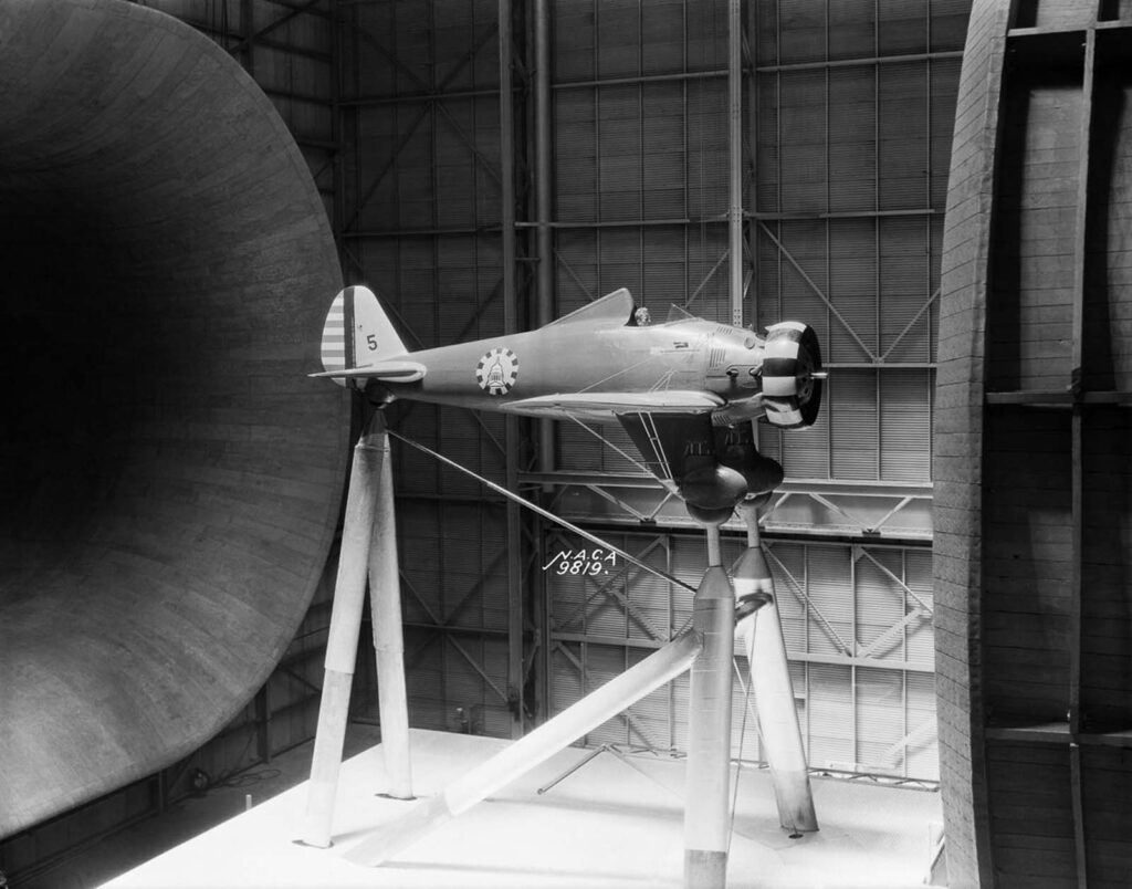

A Boeing P-26A fighter mounted in the 30 x 60 Full Scale Tunnel. Nicknamed the “Peashooter,” it was the first Army fighter to be constructed entirely of metal and to employ the low-wing monoplane configuration. 1934.
All NASA craft must undergo complete testing through one of the administration’s 42 major wind tunnels and it’s cleared for liftoff once all the parameters are reached.
These wind tunnels range from just a few inches wide to cavernous enough to test full-sized aircraft. Most of the time, large powerful fans suck air through the tube.
The object being tested is held securely inside the tunnel so that it remains stationary. The object can be an aerodynamic test object such as a cylinder or an airfoil, an individual component, a small model of the vehicle, or a full-sized vehicle.
The air moving around the stationary object shows what would happen if the object was moving through the air. The motion of the air can be studied in different ways; smoke or dye can be placed in the air and can be seen as it moves around the object.
The earliest wind tunnels were invented towards the end of the 19th century, in the early days of aeronautic research, when many attempted to develop successful heavier-than-air flying machines.
The wind tunnel was envisioned as a means of reversing the usual paradigm: instead of the air standing still and an object moving at speed through it, the same effect would be obtained if the object stood still and the air moved at speed past it.
In that way, a stationary observer could study the flying object in action and could measure the aerodynamic forces being imposed on it.

A Langley researcher observes a Sperry M-1 Messenger, the first full-scale airplane tested in the Propeller Research Tunnel. 1927.
The US Navy in 1916 built one of the largest wind tunnels in the world at that time at the Washington Navy Yard. The inlet was almost 11 feet (3.4 m) in diameter and the discharge part was 7 feet (2.1 m) in diameter. A 500 hp electric motor drove the paddle-type fan blades.
In 1931 the National Advisory Committee for Aeronautics (NACA) built a 30-foot-by-60-foot full-scale wind tunnel at Langley Research Center in Langley, Virginia. The tunnel was powered by a pair of fans driven by 4,000 hp electric motors.
The layout was a double-return, closed-loop format and could accommodate many full-size real aircraft as well as scale models. The tunnel was eventually closed and, even though it was declared a National Historic Landmark in 1995, demolition began in 2010.
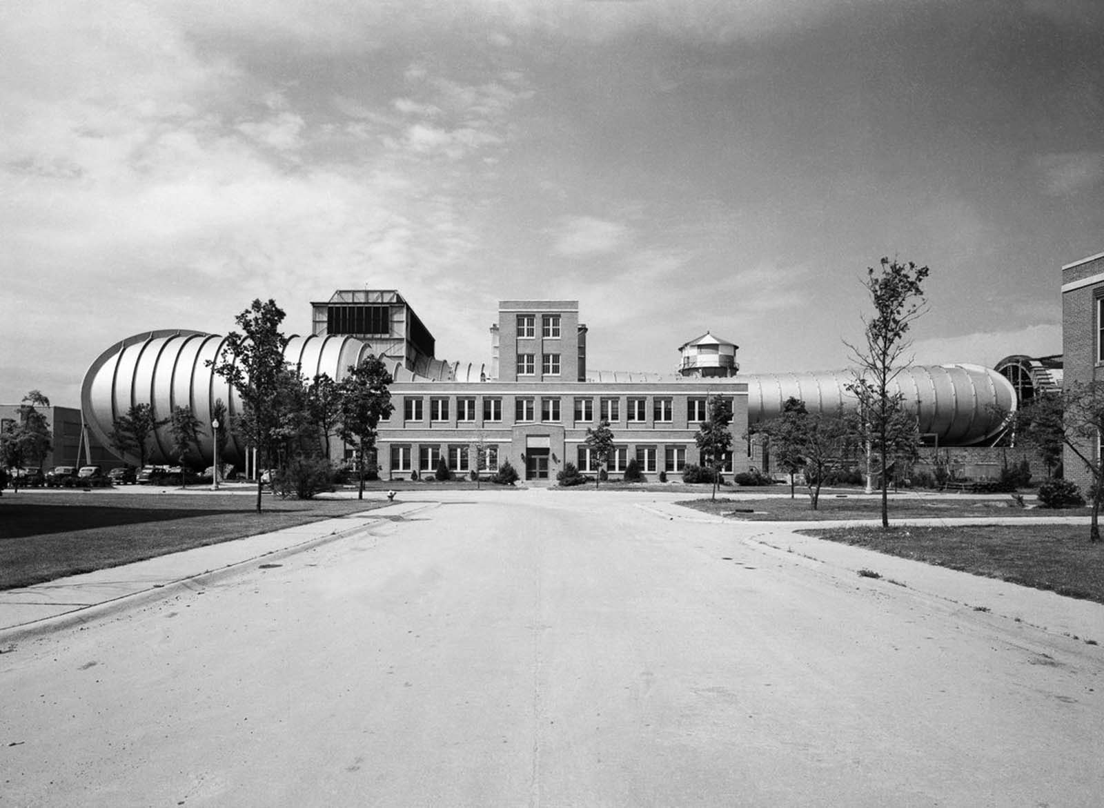
In 1941 the US constructed one of the largest wind tunnels at that time at Wright Field in Dayton, Ohio. This wind tunnel starts at 45 feet (14 m) and narrows to 20 feet (6.1 m) in diameter.
Two 40-foot (12 m) fans were driven by a 40,000 hp electric motor. Large-scale aircraft models could be tested at airspeeds of 400 mph (640 km/h).

A prototype Vought-Sikorsky V-173 airplane mounted in the Full Scale Wind Tunnel. 1941.
By the end of World War II, the US had built eight new wind tunnels, including the largest one in the world at Moffett Field near Sunnyvale, California, which was designed to test full-size aircraft at speeds of less than 250 mph and a vertical wind tunnel at Wright Field, Ohio, where the wind stream is upwards for the testing of models in spin situations and the concepts and engineering designs for the first primitive helicopters flown in the US.
Later on, specialized tunnels were developed to simulate subsonic, transsonic, supersonic and even hypersonic speeds — five times the speed of sound. Some tunnels can approximate the fiery heat of atmospheric re-entry, while others can test the effects of ice buildup at high altitudes.

A Sikorsky YR-4B/HNS-1 helicopter, the first mass-produced chopper, in the 30 x 60 Full Scale Tunnel. 1944.
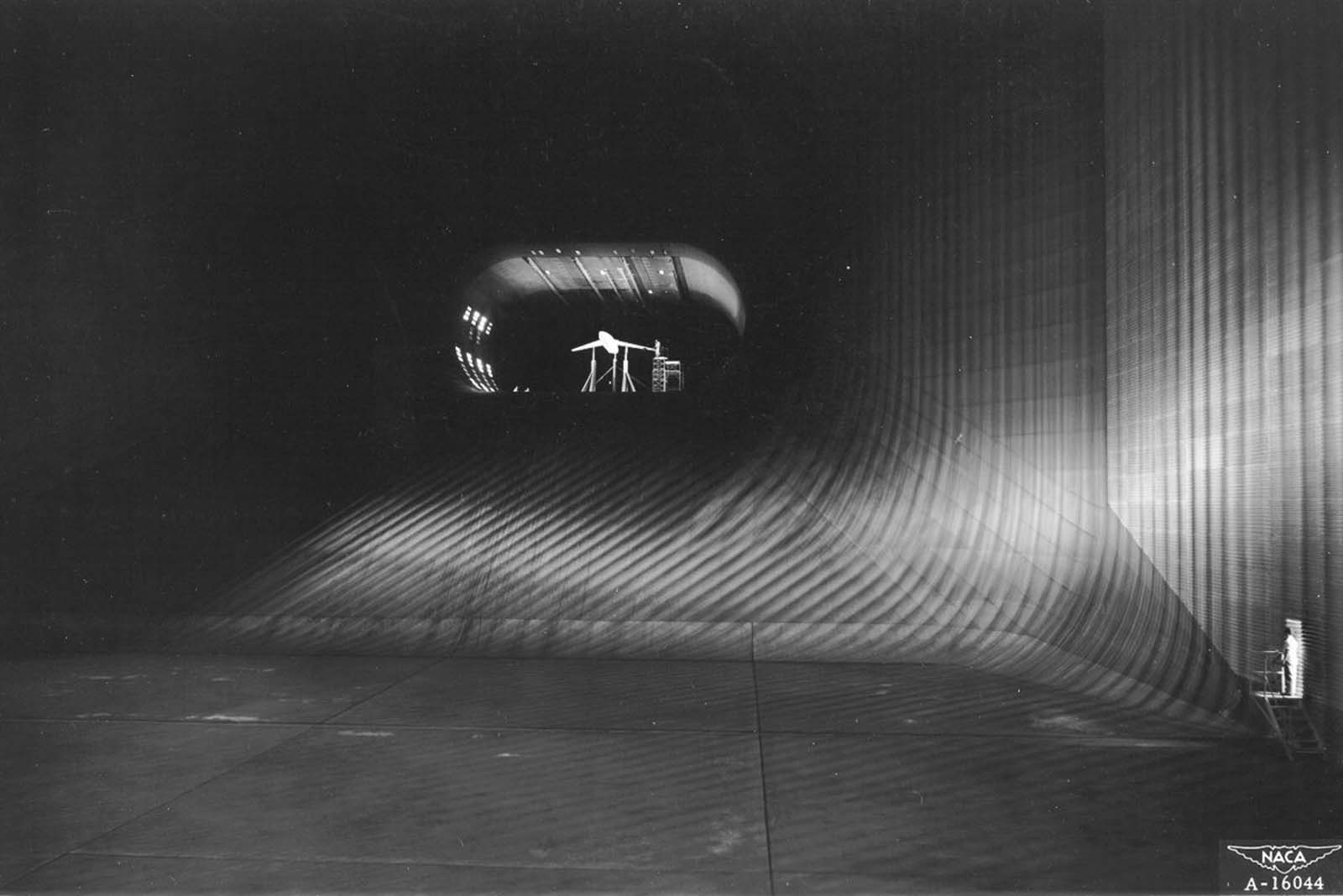
The 40 x 80-foot wind tunnel at Ames Aeronautical Laboratory, Moffett Field, California. At the time of its construction it was the largest wind tunnel in the world. 1947.
The 16-foot High Speed Tunnel at Langley Research Center. 1949.

One of three control panels in the control room of the Lewis Unitary Plan Wind Tunnel. 1955.

A 24-foot swinging valve in the 10 x 10-foot Supersonic Wind Tunnel. 1956.
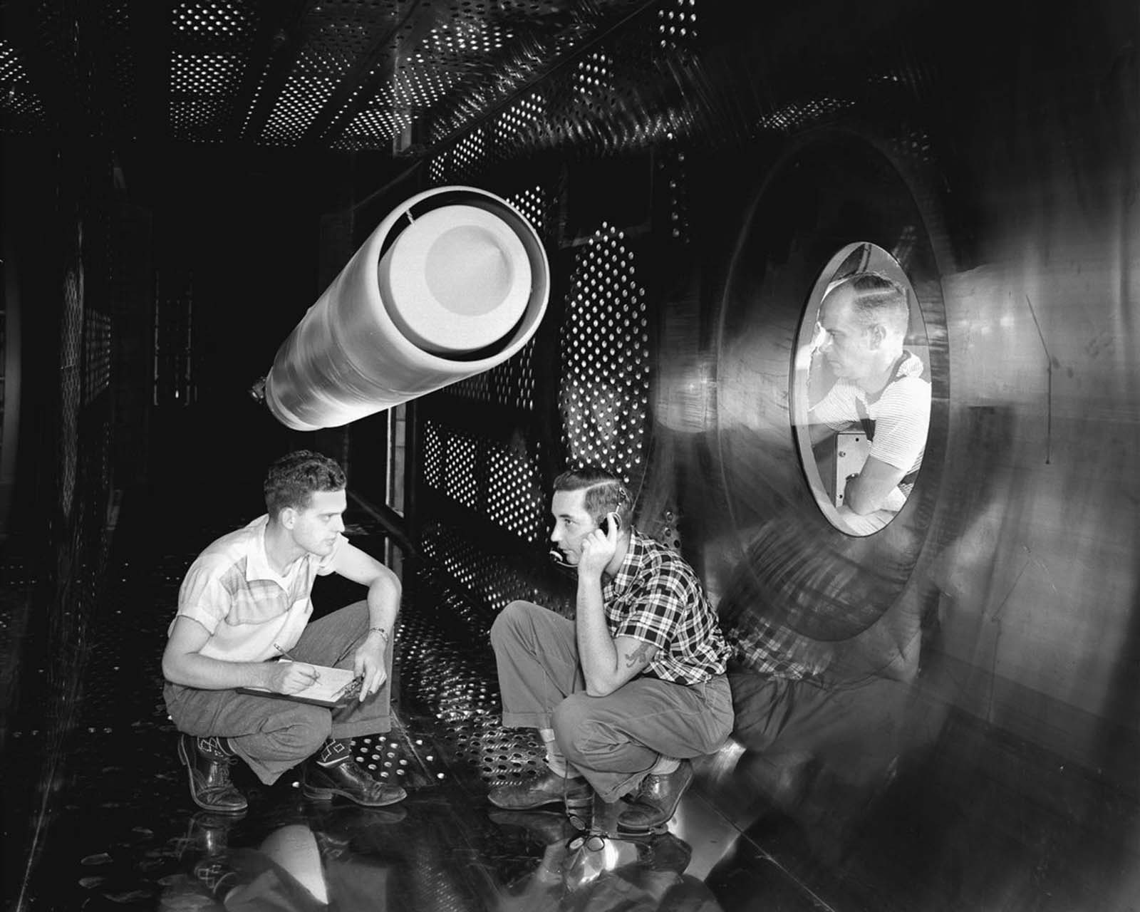
An ACN Nozzle model in the 8 x 6-foot Supersonic Wind Tunnel Test-Section. 1957.

Engineers make a check of a model of a supersonic aircraft before a test run in the 10 x 10-foot Supersonic Wind Tunnel test section. 1957.

A Mercury Capsule model in the Spin Tunnel. 1959.

Shadowgraphs of fluid disturbances around high-velocity vehicles demonstrate how a blunt-bodied vehicle produces a shockwave in front of the vehicle, which allows it to stay cooler during reentry. 1960.

A 10-story bank of vanes which turn the air around one of the four corners of the 40 x 80-foot Wind Tunnel at Ames Research Center.

A one-inch scale model of a typical supersonic airplane design is examined before being installed for sonic boom studies in the four-foot supersonic tunnel at Langley Research Center. Pressure measurements are made in the tunnel up to 50 inches away from the model, simulating altitudes up to 40,000 feet. 1960.
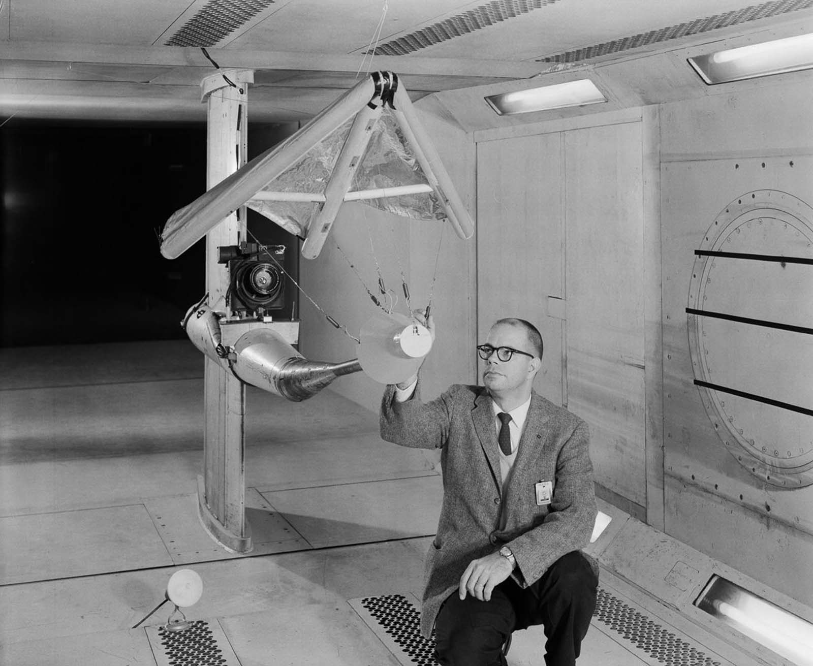
W. C. Sleeman, Jr. inspects a model of a paraglider in the 300 mph, 7 x 10-foot Wind Tunnel. The paraglider, or “Rogallo Wing,” was proposed for use in the Gemini Program. It would have allowed Gemini to make precision landings on land, rather than in the water. It failed to deploy reliably and was canceled. 1962.

Technicians install a model of an Apollo command module in the 9 x 6-foot Thermal Structures Tunnel for tests of possible heat shield materials. 1962.

A full scale model of the HL-10 lifting body mounted in the 30 x 60 Full Scale Tunnel at Langley. 1964.
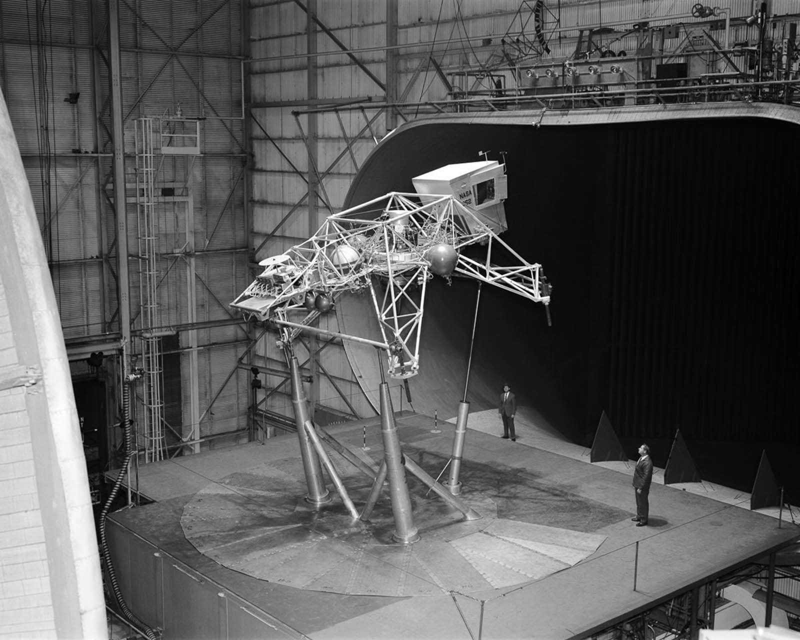
The Bell Lunar Landing Training Vehicle in the 30 x 60 Full Scale Tunnel.
The aeroshell which protected the Viking lander during its entry into the Martian atmosphere. 1973.

Thermal insulation materials for the Space Shuttle are tested at high temperatures. 1975.

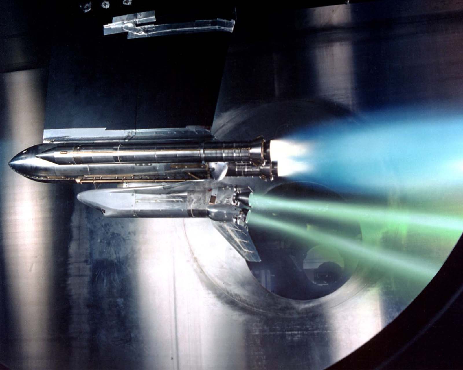
A space shuttle model undergoes a wind tunnel test simulating the ionized gasses that surround a shuttle as it reenters the atmosphere. 1975.
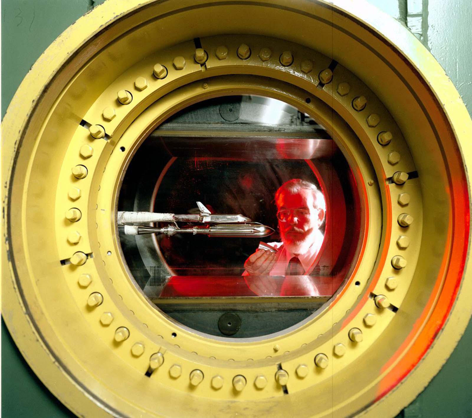
A Marshall Space Flight Center engineer holds a replica of the proposed Liquid Booster Module while observing the testing of a small Space Shuttle orbiter model at Wind Tunnel 14. 1980.

The Rutan Model 33 VariEze was built by the Model and Composites Section of Langley Research Center and then tested in the 30 x 60 Full Scale Tunnel. The craft was not built for flight, but did have an electric motor installed to drive the propeller as part of its aerodynamics study in the tunnel. 1981.

A researcher examines the ice build-up on a turboprop engine nacelle in the Icing Research Tunnel. 1983.

NASA technician W.L. Jones inspects a transport model Pathfinder I between test runs at Langley’s National Transonic Facility. 1986.

A model aircraft is tested in the Spin Tunnel. 1987.
A test of Space Shuttle main engine failure at the John H. Glenn Research Center. 1988.

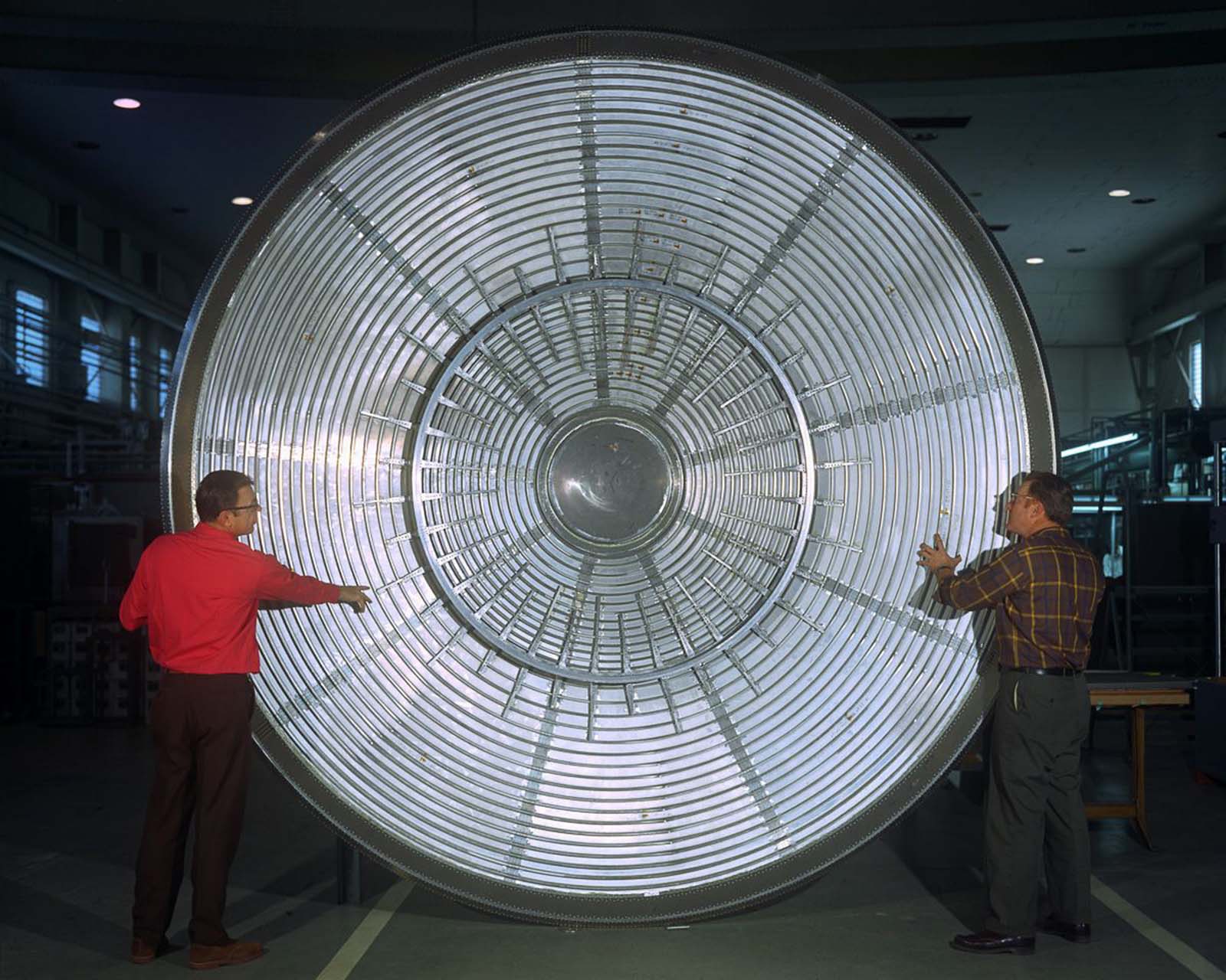
One of the two 34-foot-diameter fans in the 16-Foot Transonic Tunnel at Langley Research Center. 1990.
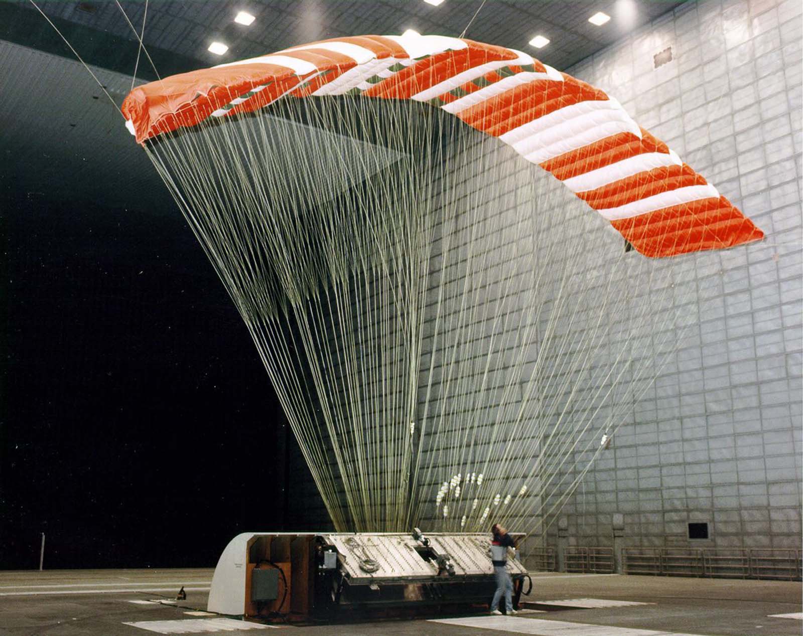
The Pioneer Aerospace Parafoil undergoes testing in the world’s largest wind tunnel, the 80 x 120-Foot Tunnel at NASA’s Ames Research Center in Mountain View, California. 1990.

Turning vanes in the 16-Foot Tunnel at Langley. 1990.

A shuttle model is magnetically suspended in the transparent hexagonal test section of the MIT/NASA Langley 6 inch MSBS. Massive power supplies are required to drive electromagnets for model position control. The low speed (Mach 0.5) wind tunnel was handcrafted from mahogany. 1991.

An F-16 model in a flow visualization test using smoke and a laser light sheet to illuminate the smoke. 1992.