From a very early age, Maurice A. Tips and his younger brother Ernest Oscar were interested in aviation. By 1909, the Belgian siblings had built their first aircraft: a canard-design, pusher biplane. The first engine installed in the aircraft proved underpowered and was replaced with a Gnome rotary. The engine was geared to two shafts, each driving a two-blade pusher propeller. Although the aircraft made some flights, its handling was unsatisfactory, and the design was not developed further. The aircraft did possess unique concepts, a theme continued in Maurice’s subsequent designs.

Rear view of Maurice and Ernest Oscar Tips’ 1909 biplane pusher. The aircraft was unable to fly with its original Pipe V-8 engine, but the lighter Gnome rotary enabled the aircraft to takeoff. Note the central gearbox that provided power to the shafts that turned the propellers via right-angle drives.
After the 1909 aircraft, Maurice refocused his efforts on aircraft engines. By 1911, Maurice had designed the first in a series of “valveless” rotary engines. All of Tips’ engines used a rotary valve system for cylinder intake and exhaust. Unfortunately, documentation on these engines is nearly non-existent; their exact order of development and specifications are not known with certainty.

Drawings of the 25 hp (19 kW) Tips engine of 1912. Air was drawn through the rotating suction tubes (5) which enable the intake port (14) and exhaust port (13) to align with the cylinder. The suction tubes were geared (9 and 10) to the stationary crankshaft (4).
The first engine was a seven-cylinder rotary that produced 25 hp (19 kW). The engine had a 2.76 in (70 mm) bore, a 4.33 in (110 mm) stroke, and a displacement of 181 cu in (3.0 L). Hollow “suction tubes” took the air/fuel mixture from the engine’s crankcase and delivered it to the cylinders. Each suction tube was geared to the engine’s fixed crankshaft. The suction tubes would spin at half the speed of the crankcase as it rotated. The top of the suction tube had two passageways. Each passageway would align with a common port near the top of the cylinder once every two revolutions of the crankcase. One passageway aligned to allow the air/fuel mixture to flow from the suction tube and into the cylinder. The second passageway aligned to allow the exhaust gases to flow from the cylinder out into the atmosphere.
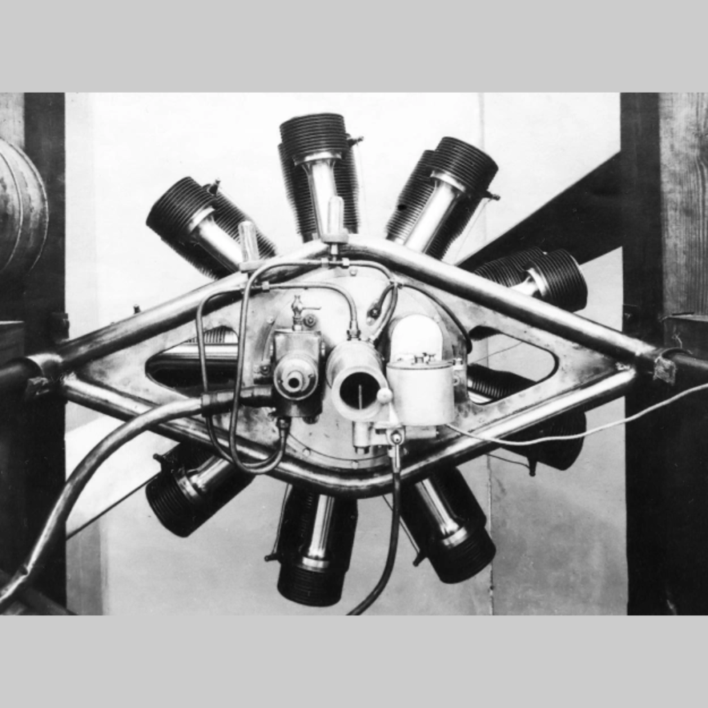
The 25 hp (19 kW) Tips “valveless” rotary engine was installed in a monoplane built by Henri Gérard. It appears the aircraft was completed around 1913. However, the performance results of the engine and aircraft have not been found. As history unfolded, this was the only Tips engine installed in an aircraft.

Henri Gérard and his mechanic by Gérard’s Tips-powered monoplane. The engine was a 25 hp (19 kW) seven-cylinder “valveless” rotary. Note the spark plug protruding from the top of each cylinder. (Tips Family Archive via Vincent Jacobs)
Maurice continuously refined the design of “valveless” rotary engines. In late 1912, two larger versions of the seven-cylinder engine were planned. A 50 hp (37 kW) version had a 4.33 in (110 mm) bore, a 4.72 in (120 mm) stroke, and a displacement of 487 cu in (8.0 L). The largest engine produced 70 hp (52 kW) and had a 4.41 in (112 mm) bore, a 5.12 in (130 mm) stroke, and a displacement of 547 cu in (9.0 L). An advertisement stated that all three engines would be displayed at the Salon de l’Automobile held in Brussels, Belgium in January 1913. In addition, the 25 hp (19 kW) engine was used to power a Tips airboat that was displayed at the show.
Engine development continued throughout 1913 and 1914. The most obvious change was that the suction tube was moved to be parallel with the cylinder, rather than at an angle as seen in the earlier engines. The newer engine design had an updated drive for the suction tubes, and the air/fuel mixture no longer passed through the crankcase; rather, it was delivered through a hollow extension of the crankshaft to a space under the suction tubes. A nine-cylinder engine of this design was built, but it is not clear if the engine was built in Europe or the United States; it was most likely built in the US.

The 1913 (left) and 1914 (right) versions of the Tips rotary engine. The major changes were to the suction tube drive and rotary valve. The small tube (no. 14 on the 1913 engine and no. 40 on the 1914 engine) in the stationary crankshaft extension provided oil to the crankshaft and connecting rod.
When World War I broke out, Maurice and Ernest Tips fled Belgium. Ernest made his way to Britain, where he worked with Charles Richard Fairey and helped start the Fairey Aviation Company in 1915. Ernest would return to Belgium in 1931 to start the Fairey subsidiary, Avions Fairey. He also produced the Tipsy series of light aircraft.
Maurice Tips traveled to the US in October 1915 and continued to design aircraft engines. It is quite possible that the nine-cylinder engine was built once Tips had established himself in the US. The engine had a 4.92 in (125 mm) bore and a 5.91 in (150 mm) stroke. It displaced 1,011 cu in (16.6 L) and produced 110 hp (82 kW). The nine-cylinder engine was approximately 35 in (.89 m) in diameter and weighed 290 lb (132 kg). A smaller nine-cylinder engine was designed, but it is not clear if it was built. The smaller engine had a 4.92 in (125 mm) bore and a 5.51 in (140 mm) stroke. It displaced 944 cu in (15.5 L) and produced 100 hp (75 kW).

Rear view of the 110 hp (82 kW) nine-cylinder Tips “valveless” rotary engine. Air was drawn in through the hollow extension to the crankshaft where it mixed with fuel. Ports in the crankshaft extension led to a distribution chamber at the back of the engine. The air/fuel mixture was drawn into the suction tube behind each cylinder and then into the combustion chamber. (Tips Family Archive via Vincent Jacobs)
For more power, Maurice had the idea of coupling two 110 hp (82 kW) nine-cylinder engines in tandem to make an 18-cyinder power unit. The two engine sections would be placed front-to-front and rotate in the same direction. The engines would be suspended some 20 in (508 mm) below the propeller shaft. A Renold Silent (inverted tooth) drive chain positioned between the two engines would deliver power to the propeller shaft. By varying the size of the drives, a propeller speed reduction could be achieved. Drawings show a 5 in (127 mm) drive gear and a 7.5 in (191 mm) gear on the propeller shaft, which would give a .667 speed reduction. The tandem 18-cylinder engine had an output of 220 hp (164 kW) and was 606 lb (275 kg). The power unit was 62 in (1.57 m) long and 40 in (1.02 m) in diameter, not including the propeller shaft. It is unlikely that a tandem engine was built.
In 1917, The Tips Aero Motor Company was founded in Woonsocket, Rhode Island. That same year, Maurice applied for patents covering his new engine design, which incorporated many concepts from the earlier engines. Rather than a tandem engine, the new Tips engine was a single, 18-cylinder power unit. The rotary engine had two rows of nine cylinders and was housed in a stationary frame. The new engine employed both water and air cooling. The cylinders were arranged in pairs, with one in the front row of the engine and the other in the rear row. The crankshaft had only one throw, and the pistons for both cylinders in a pair were at top dead center on their compression strokes at the same time. The engine’s compression ratio was 5.25 to 1. Each cylinder had one spark plug at the center of its combustion chamber. The spark plugs were fired by two magnetos mounted to the front of the engine and driven from the propeller shaft.

The Tips Tandem engine consisted of two nine-cylinder engines coupled together. An inverted tooth chain between the engines delivered power to the propeller shaft. (Tips Family Archive via Vincent Jacobs)
Most rotary engines had a fixed crankshaft and a crankcase that rotated. This arrangement created much stress on the crankshaft and crankcase and also imposed severe gyroscopic effects on the aircraft. The Tips engine employed several unique characteristics to resolve the drawbacks of traditional rotary engines. The crankshaft of the Tips engine rotated and was geared to the propeller shaft. The propeller shaft was geared to the crankcase, which allowed it to rotate in the opposite direction from the crankshaft and propeller. The end result was that when the crankshaft was turning at 1,800 rpm, the propeller would turn at 1,080 rpm, and the crankcase would rotate at 60 rpm in the opposite direction. Rotary engines in which the crankshaft and crankcase rotate in opposite directions and at different speeds are often called bi-directional or differential rotary engines.
The propeller shaft of the Tips 18-cylinder engine was geared to the crankshaft at a .600 reduction; the crankshaft gear had 18 teeth, and the propeller shaft’s internal gear had 30 teeth. For crankcase rotation, the 17 teeth on the propeller shaft gear engaged 51 teeth on one side of a countershaft to give a .333 gear reduction. The other side of the countershaft had 11 teeth that meshed with a 66-tooth internal gear attached to the crankcase and resulted in a further .167 reduction. Having the propeller and crankshaft rotating in opposite directions not only eliminated the gyroscopic effect inherent to conventional rotary engines, but it also neutralized the gyroscopic effect created by the propeller attached to a fixed engine.

The 18-cylinder Tips engine of 1917 was far more complex than the earlier engines. Note the paired cylinders separated by the rotary valve (24). The propeller shaft (10) was geared to the crankshaft (7) via reduction gears (8 and 9). The crankcase was geared to the propeller shaft via a countershaft (16).
On the exterior of the cylinder castings were numerous cooling fins. In addition, internal passageways for water cooling were in the cylinder castings. Between each pair of cylinders were a series of air passageways to further augment cooling. The engine did not have a water pump; rather, thermosyphoning and the relatively slow rotation of the crankcase enabled the circulation of cooling water from the internal hot areas of the cylinders out toward the cooling fins on the exterior of the cylinders. The engine’s rotation also aided oil lubrication from the pressure-fed crankshaft to the rest of the engine. The oil pump and carburetor were located on the stationary frame at the rear of the engine.
A flange was positioned on the crankshaft, between the connecting rods of the cylinder pair. Mounted on the flange via ball bearings was an eccentric gear with 124 teeth on its outer edge. Attached (but not fixed) to the crankcase was a master valve gear that had 128 teeth on its inner edge. The gears meshing with an eccentric action resulted in the master valve gear turning four teeth per revolution of the crankshaft. On the outer edge of the master valve gear was a bevel gear with 128 teeth. These teeth engaged a 16-tooth pinion attached to a rotary valve positioned between each cylinder pair. The four teeth per revolution of the master valve gear acting on the 16-tooth rotary valve resulted in the rotary valve turning at a quarter engine speed. Each hollow rotary valve had two intake ports and two exhaust ports.

On the left is the rotary valve shown with the intake ports aligned (Fig 3). The air/fuel mixture entered the valve through ports in its lower end (27a). On the right is the valve with the exhaust ports aligned (Fig 5). Fig 4 shows a cross section of the rotary valve with intake ports (28), exhaust ports (29), and passageways for the flow of cooling water (30). Fig 8 shows the valve gear drive. The crankshaft (7) turned an eccentric gear (44) that meshed (42 and 41) with a gear mounted to the crankcase. The result is that a bevel gear (27) engaged a gear screwed to the bottom of the rotary valve (26 on Fig 3) and turned the valve once for every four revolutions of the crankshaft.
Air was drawn in through a carburetor at the rear of the engine. The air/fuel mixture flowed through a manifold bolted to the cylinder casting and into a passageway that led to a chamber around the lower part of the rotary valve. Holes in the valve allowed the air to flow up through its hollow middle and into the cylinder when the intake ports aligned. As the valve rotated, the exhaust ports would align with the cylinder, allowing the gases to escape out the top of the valve head and into the atmosphere. Passageways in the lower part of the rotary valve head brought in cooling water from the cylinder’s water jacket. Water flowed up through the rotary valve and back into the cylinder’s water jacket. The rotary valve was lubricated by graphite pads and held in place by a spiral spring and retaining cap around its upper surface.
The 18-cylinder Tips engine had a 4.5 in (114 mm) bore and a 6.0 in (152 mm) stroke. The engine displaced 1,718 cu in (28.1 L) and produced 480 hp (358 kW) at 1,800 rpm. The Tips engine weighed 850 lb (386 kg). At speed, the engine consumed 22 gallons (83 L) of fuel and 3 gallons (11 L) of oil per hour. The oil consumption was particularly high, even for a rotary engine, but the Tips engine was larger and more powerful than other rotary engines.

Rear view of the 480 hp (358 kW) Tips engine shows the extensive fining (22) that covered the engine. The fining and air passages (23) combined to turn the whole engine into a radiator to cool the water that flowed through the engine via thermosyphoning and centrifugal force.
In 1919, the engine was mentioned in a few publications. In 1920, Leo G. Benoit, Technical Manager at Tips Aero Motors, passed away. Benoit was said to be in charge of the engine’s design and construction. No further information regarding the engine and no images of the engine have been found. This lack of information could mean that the 480 hp (358 kW) Tips engine was never built. However, given the detailed description of the engine and that it was worked on from 1917 to at least 1920, the possibility certainly exists that the engine was built and tested.
Sometime before World War II, Maurice Tips returned to Belgium. He continued to design engines and applied for a patent on a rotary piston engine in 1938. This engine was not designed for aircraft use and bore no similarities to his early aircraft engines.

Maurice Tips stands next to the unfinished crankcase casting for the 18-cylinder differential rotary engine. The holes in the crankcase’s outer diameter were for the rotary valves. The holes in the crankcase’s face were for water radiators, and the holes inside of the crankcase were for the cylinders. It is not known if a complete engine was built. (Tips Family Archive via Vincent Jacobs)